The AM Forum
May 06, 2024, 02:19:14 PM *
Welcome, Guest. Please login or register.

Login with username, password and session length
 
   Home   Help Calendar Links Staff List Gallery Login Register  
Pages: [1]   Go Down
  Print  
Author Topic: New Xmtr - Simple, bandswitched class E-Z 500 watts (With Pictures)  (Read 5619 times)
0 Members and 1 Guest are viewing this topic.
steve_qix
Contributing
Member
*
Offline Offline

Posts: 2592


Bap!


WWW
« on: January 18, 2006, 10:36:25 PM »

Here is a very simple, foolproof, high power (up to 500 watts carrier output), bandswitched (80/160 - 40 meters coming!) class E transmitter.

This is probably the easiest high power transmitter yet.  I was able to construct two of these RF decks in one weekend!  I run this
transmitter at 45 volts at 10 amperes.  It will actually do 12 amperes, however my modulator will not  Cool

There is exactly one tuned circuit in the whole thing - the output tank. Everything else is digital and broad band (100khz - 8 mhz), right
up to and including the gates of the final MOSFETs.  The RF amplifier uses inexpensive IXYS MOSFET driver devices connected directly
to the gates of the final RF amplifier MOSFETs.  The drivers take a standard TTL input at the operating frequency from 74 series logic,
and this signal is supplied from a simple circuit consisting of a quad NAND gate and an OP-amp.  This takes 3 volts or so of RF at the
transmit frequency from a VFO or other RF source.

The design is a single ended push pull, resulting in low harmonic output and easier filtering.

This first picture is an overall view of the transmitter, clip leads and all.  Note the RF tank components to the left; a variable
inductor, tuning capacitor and loading capacitor.  I will use a switched coil in the actual implementation.
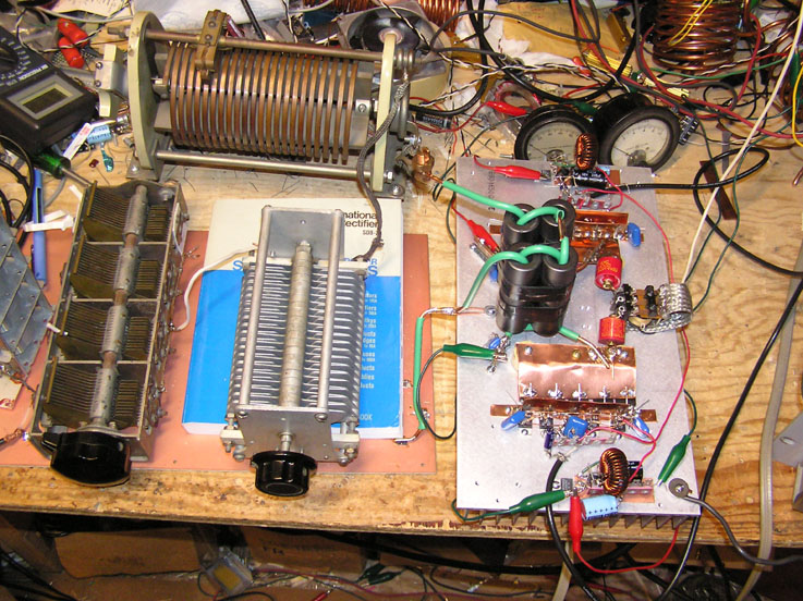

Click here to see the full sized image

The next picture is a close up of  the RF amplifier components, mounted on the heat sink
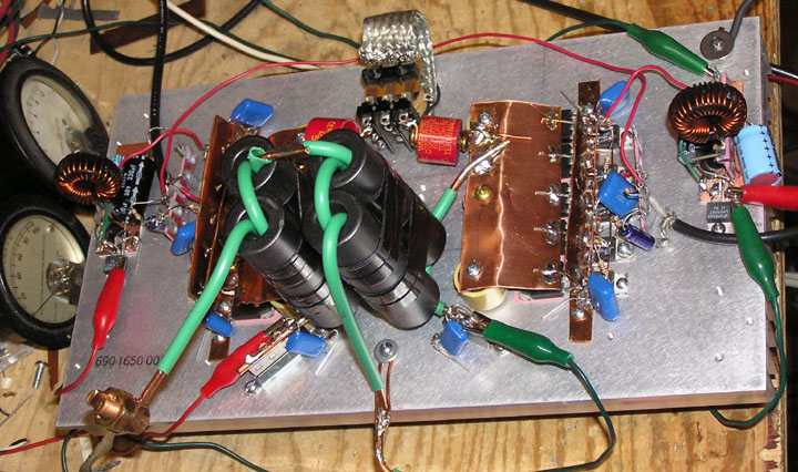
Click here to see the full size picture

This thing is SIMPLE.  I soldered it together, did a QUICK 'scope check of the stages, and went on the air (I used an already built modulator
and power supply).  Works like a charm.

The goal of this project was twofold: 

1) to come up with a very reproducible, uncomplicated, multiband RF amplifier - and -
2) to create a virtually indestructable transmitter by incorporating inexpensive protection devices in all sections of the RF amplifier,
and shutdown circuitry where appropriate.

The first goal has been achieved, and I am currently running the "torture tests" (shorting the antenna, disconnecting the antenna, mistuning (very badly), overmodulating (clipping the modulator at 150% positive modulation) while doing all of the aformentioned tests, etc).  I will tollerate no device failures.

Assuming all goes as planned, I will be documenting this design - AND - this will be the basis of the QST article.  Former designs (mine included),
required too much technical knowledge and "tinkering" to be suitable for a "first time" AM project.  Now, I am reasonably confident that
anyone who has a relatively modest technical background, but who can otherwise solder components properly, and follow directions should be
able to build one of these things and get it on the air.

Oh well - another old buzzard transmission.

Regards,

Steve


Logged

High Power, Broadcast Audio and Low Cost?  Check out the class E web site at: http://www.classeradio.org
w3jn
Johnny Novice
Administrator
Member

Offline Offline

Posts: 4611


« Reply #1 on: January 19, 2006, 07:00:01 AM »

When you gonna document the switch mode mudulator you had in your converted Ranger, Steve?
Logged

FCC:  "The record is devoid of a demonstrated nexus between Morse code proficiency and on-the-air conduct."
WA1GFZ
Member

Offline Offline

Posts: 11151


« Reply #2 on: January 19, 2006, 12:31:51 PM »

Steve,
Where is the driver? All I see is a coax to the gates. How did you configure the driver chips and how many did you use per phase?  I notice your 2 phases are getting closer to each other.......
Logged
K3ZS
Member

Offline Offline

Posts: 1036


« Reply #3 on: January 19, 2006, 04:06:25 PM »

I heard you on 75M yesterday talking about this.  Were you using it then, it sounded great whatever you were using.  I have been looking around for a higher power transmitter.  With epay prices on the boat anchors, and a more modern junk box, I think this is just what will get  more hams on higher power AM.
Logged
W1DAN
Contributing
Member
*
Offline Offline

Posts: 904


« Reply #4 on: January 19, 2006, 05:46:27 PM »

Hi Steve:

It looks like a masterpiece...not!

But it sure sounded good and you had a very strong signal in Natick.

Looking forward to the tech info. Lemme know if I can help in any way.

73
Dan
W1DAN


Logged
steve_qix
Contributing
Member
*
Offline Offline

Posts: 2592


Bap!


WWW
« Reply #5 on: January 19, 2006, 06:15:03 PM »

Steve,
Where is the driver? All I see is a coax to the gates. How did you configure the driver chips and how many did you use per phase?  I notice your 2 phases are getting closer to each other.......

Hi Frank - the driver chips for the output MOSFETs are there, on the heat sink.  They are 5 pin TO220 devices.  These take a TTL input (coming through the coax), and this signal comes from a schmidt trigger / inverter / pulse width control combination.  Into this is fed a 3 volt RF signal at the desired transmit frequency.  There really is NOT much to it Cool


When you gonna document the switch mode mudulator you had in your converted Ranger, Steve?

Yes, I do need to do more work on that project :-)  It works very well, but was rather hastily built.  It's somewhat complex.   Oh, what we
are talking about is a combination switching power supply / modulator for a 500 watt (input) transmitter I designed and built last year.  What makes
this unique is there is no power transformer, and the output is isolated from the AC line, so nothing has to float.  The modulator/power supply
delivers up to 135 volts peak at 30 amps.  Carrier level was typically set at 45 volts.  The ripple frequency was 220kHz.

Hi Steve:

It looks like a masterpiece...not!

But it sure sounded good and you had a very strong signal in Natick.

Looking forward to the tech info. Lemme know if I can help in any way.

73
Dan
W1DAN


Make this thing neat  Roll Eyes  This is something I cannot seem to master, no matter how hard I try.  It sure does WORK well :-)

Thanks and Regards,

Steve
Logged

High Power, Broadcast Audio and Low Cost?  Check out the class E web site at: http://www.classeradio.org
w3jn
Johnny Novice
Administrator
Member

Offline Offline

Posts: 4611


« Reply #6 on: January 19, 2006, 07:02:12 PM »

I'm really looking forward to the SMPS/modulator, Steve, that'll get me off my dead ass for sure to get mine done.

73 John
Logged

FCC:  "The record is devoid of a demonstrated nexus between Morse code proficiency and on-the-air conduct."
WA1GFZ
Member

Offline Offline

Posts: 11151


« Reply #7 on: January 19, 2006, 08:52:18 PM »

Steve, do you have 1 driver per final FET? I can see the chips behing the final fets
but only looks like there are 4 drivers. I would drive the drivers with a totem pole driver off a flip flop and put a good resistive load on the inputs to hold it stable.
Man that would make a good predriver for the 160 meter rig. Good find on the totem poles!  fc
Logged
W1UJR
Guest
« Reply #8 on: January 19, 2006, 09:36:17 PM »

Here is a very simple, foolproof, high power (up to 500 watts carrier output), bandswitched (80/160 - 40 meters coming!) class E transmitter.

Regards,

Steve


Steve, you're amazing!

Not only for your technical ability, which is spectacular, but the fact that things you built work like that!
Man, it seems if I don't dot every "i" and cross every "t" in my projects they never work.
You on the other hand have the air variable sitting above a copper plate (ground plane) with a paper manual in between (capacitive coupling?) and it makes 500 watts, go figure!  Cheesy

Now, how about a project in kit form for those of us who eschew the "dead bug" construction?

-Bruce W1UJR
Logged
WA1GFZ
Member

Offline Offline

Posts: 11151


« Reply #9 on: January 19, 2006, 09:49:20 PM »

20 bucks
a handful of fets
a bag of driver chips
and 3 bags of radio shack clip leads


Hey Bruce, Steve has really improved in the past few years. I bet you he has tapped more holes in the past 4 years then the past 40. Super glue doesn't work worth a darn on sil pads and heat sinks.


Logged
Glenn NY4NC
Guest
« Reply #10 on: January 20, 2006, 10:14:44 AM »

I for one, really appreciate your efforts Steve!.... This latest 160/80 banswitched design just might get me to actually build a class-e rig!....... You mentioned 40 meters, do you mean the final design will do all three bands?
That would be most excellent!  Cheesy


Here is a very simple, foolproof, high power (up to 500 watts carrier output), bandswitched (80/160 - 40 meters coming!) class E transmitter.

Former designs (mine included), required too much technical knowledge and "tinkering" to be suitable for a "first time" AM project.  Now, I am reasonably confident that anyone who has a relatively modest technical background, but who can otherwise solder components properly, and follow directions should be able to build one of these things and get it on the air.

Oh well - another old buzzard transmission.

Regards,

Steve


Logged
WA1GFZ
Member

Offline Offline

Posts: 11151


« Reply #11 on: January 20, 2006, 11:19:28 AM »

Glenn,
The driver has always been the big deal. These parts have improved and the cost has dropped over the years. It is good to see Steve has found another good part to play with. My 160 meter rig still has TO3 case FETs in the predriver. These drivers may replace them allowing me to double my output power. Good Find Steve!
Logged
Pages: [1]   Go Up
  Print  
 
Jump to:  

AMfone - Dedicated to Amplitude Modulation on the Amateur Radio Bands
 AMfone © 2001-2015
Powered by SMF 1.1.21 | SMF © 2015, Simple Machines
Page created in 0.041 seconds with 18 queries.