Here is a very simple, foolproof, high power (up to 500 watts carrier output), bandswitched (80/160 - 40 meters coming!) class E transmitter.
This is probably the easiest high power transmitter yet. I was able to construct two of these RF decks in one weekend! I run this
transmitter at 45 volts at 10 amperes. It will actually do 12 amperes, however my modulator will not

There is exactly one tuned circuit in the whole thing - the output tank. Everything else is digital and broad band (100khz - 8 mhz), right
up to and including the gates of the final MOSFETs. The RF amplifier uses inexpensive IXYS MOSFET driver devices connected directly
to the gates of the final RF amplifier MOSFETs. The drivers take a standard TTL input at the operating frequency from 74 series logic,
and this signal is supplied from a simple circuit consisting of a quad NAND gate and an OP-amp. This takes 3 volts or so of RF at the
transmit frequency from a VFO or other RF source.
The design is a single ended push pull, resulting in low harmonic output and easier filtering.
This first picture is an overall view of the transmitter, clip leads and all. Note the RF tank components to the left; a variable
inductor, tuning capacitor and loading capacitor. I will use a switched coil in the actual implementation.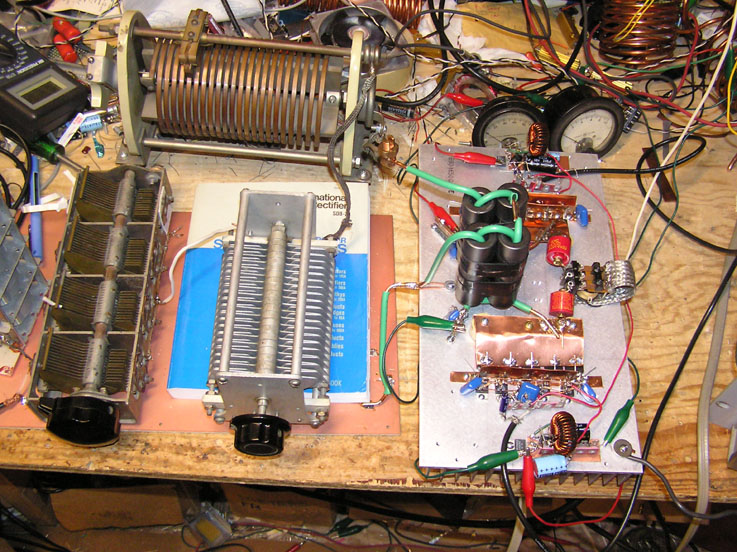 Click here to see the full sized imageThe next picture is a close up of the RF amplifier components, mounted on the heat sink
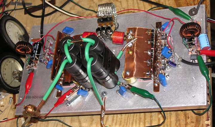 Click here to see the full size picture
This thing is
SIMPLE. I soldered it together, did a QUICK 'scope check of the stages, and went on the air (I used an already built modulator
and power supply). Works like a charm.
The goal of this project was twofold:
1) to come up with a very reproducible, uncomplicated, multiband RF amplifier - and -
2) to create a virtually indestructable transmitter by incorporating inexpensive protection devices in all sections of the RF amplifier,
and shutdown circuitry where appropriate.
The first goal has been achieved, and I am currently running the "torture tests" (shorting the antenna, disconnecting the antenna, mistuning (very badly), overmodulating (clipping the modulator at 150% positive modulation) while doing all of the aformentioned tests, etc). I will tollerate no device failures.
Assuming all goes as planned, I will be documenting this design - AND - this will be the basis of the QST article. Former designs (mine included),
required too much technical knowledge and "tinkering" to be suitable for a "first time" AM project. Now, I am reasonably confident that
anyone who has a relatively modest technical background, but who can otherwise solder components properly, and follow directions should be
able to build one of these things and get it on the air.
Oh well - another old buzzard transmission.
Regards,
Steve


