N4LTA
Contributing
Member

 Offline Offline
Posts: 1075
|
 |
« on: March 25, 2012, 08:54:00 PM » |
|
I finally got some time to put all the stuff together and try a test. The transmitter power output is 31 watts carrier after a hefty voltage drop in the modulation reactor (about 25 volts). I tuned up the transmitter into the dummy load and then hooked up a 150 watt amplifier in bridge mode and a CD player as the audio source. The modulator has a Hammond 125GSE SE output transformer in reverse and a couple of 30H 100 mA chokes in parallel as a modified Heising reactor. I also have a 3 diode negative peak limiter with a 50 volt keep alive variable voltage supply. Modulation was very smooth and the amp easily pushed it to 100% positive and it sounded good (very good considering I was monitoring the signal with an ICOM R71. I have very little experience with AM modulation so I need a little help. I could not see that the negative peak limiter was doing much of anything - so I must not be operating it correctly. The carrier unmodulated was about 50 or so volts above ground - 100 volt pp with no modulation. I could drive the modulator until the peaks reached about 100 volts - 200 V PP with no negative modulation above 100% (I think) - The modulator could drive the peaks above 150 volts - 300 V PP and higher but with negative modulation severely above 100% and at that high level - the Bird watt meter went from about 31 watts to pulsing above 50 watts. Cranking the keep alive voltage from 0-55 volts didn't seem to do much or if it did it was difficult to see. The Bird watt meter did not (or just barely) moved at 100 % modulation The good news is the 125GSE and the modulation choke did not get warm and I am sure the solid state amp was doing over 100 watts out. I would appreciate any comments on what is happening at higher than 100% positive modulation and what I can expect with the 3 diode negative peak limiter and keep alive voltage. I hap attached a couple of photos - don't laugh too much at the workbench.  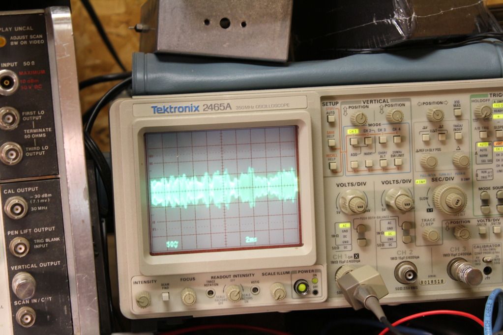 Pat N4LTA |
|
|
|
|
 Logged
|
|
|
|
Opcom
Patrick J. / KD5OEI
Contributing
Member
Offline
Posts: 8315

|
|
« Reply #1 on: March 25, 2012, 09:59:11 PM » |
|
That's very interesting work. Can you feed an audio sine wave in, like 400Hz or 1KC, sync the scope to the sine wave, and show us scope shots explaining the various conditions in your post? That would be the best way for us to help. Otherwise we can't really see what you are doing.
Why not put the 30H chokes in series? Mod reactor is usually 30-60H and 15H seems rather little. What is the lowest frequency you expect to use and the impedance of the load presented to the modulator?
|
|
|
|
|
Logged
|
Radio Candelstein - Flagship Station of the NRK Radio Network.
|
|
|
KA3EKH
Member
Offline
Posts: 778
|
|
« Reply #2 on: March 25, 2012, 10:07:11 PM » |
|
At the risk of having all the greater minds on the list point out my own ignorance let me propose a couple test that can be entertaining. First using a local receiver to monitor the transmitter is not always the best thing to do, many receivers overload or distort when in the proximity of a transmitter. Be cretin you receiver is way decoupled! Second you wont see big differences on your thru line wattmeter between no and 100% modulation, you will see differences but not like the 200% increase in output power you would expect at 100% modulation. Maybe a diode detector set up to drive an amplifier or a scope can be more fun but then you never know how good that is unless you sweep it. I always like doing audio sweeps with just plain sine wave, take a sample from the output and feed the scope just be careful to isolate it and then look at the carrier with no modulation and drive the input until you get a 100% modulation waveform or distortion of the sine wave. With a dual trace scope you can put the incoming audio to the transmitter on one trace and the RF sample on the other. Use the channel with the incoming audio to provide the trigger, a trick on learned on this reflector that way useful when dealing with modern digital scopes. If you get real good play with the amplitude controls on the scope and put the two traces on top of each other and you have a hillbilly distortion analyzer. This will give you some idea of distortion and the transmitters ability to reproduce a sine wave at 100% modulation over a wide range of frequencies. Driving the audio further will allow you to see if your negative peak stuff is working and what manner of weird stuff occurs when you overdrive the transmitter and if you have a spectrum analyzer available just look what happens when you kick the negative peaks! Dont know if any of this helps or not and hope that none of my backwoods stuff has been a waste of your time.
|
|
|
|
|
Logged
|
|
|
|
N4LTA
Contributing
Member
Offline
Posts: 1075
|
|
« Reply #3 on: March 25, 2012, 11:06:00 PM » |
|
The 30H chokes are rated at 100mA so I paralled them for 15H at 200mA. The modulating impedance is low, about 2 Kohms , so I hope that 15H is close enough. In series they will cause too much voltage drop. Seems to be working OK although I can series 2 10H 200 mA chokes if I need to.
My main questions is how high can I modulate on the high side if I have the audio drive and how does the 3 diode neg peak limiter adjust with respect to the keep alive voltage?
I would think that I should see little power of the Bird meter variation at 100% modulation if the output stage is linear and that is what I am seeing? When I overdrive it very hard - I see the output power on the Bird swinging with modulation and power peaks almost double.
How hard can I expect to drive it and the limiter cut the negative peaks to less than 100%
I have Steves (dual neg and pos) modulation meter about half done. Hope to have it working in a week or so.
The R71 antenna is actually monitoring pretty well I think. It is an active probe located over 400 feet away and very well decoupled and shielded It is my longwave antenna with two very good common mode chokes and good double shielded coax. I have gone to great lengths to isolate it from the house and all the RF crap in the house.
I'll do some scope shots with the signal generator modulating and try the hillbilly method tomarrow. This was a first try tonight and I wanted to hear it at least. I didn't crank up the spectrum analyzer either - really all that I had time to do was look at the 100% guesstimate and then overdrive it hard. The 125GSE impressed though as 100 watts plus didn't seem to phase it.
Pat
N4LTA
|
|
|
|
|
Logged
|
|
|
|
The Slab Bacon
Member
Offline
Posts: 3934
|
|
« Reply #4 on: March 26, 2012, 10:47:10 AM » |
|
Pat,
On your scope pattern, you need to post a dead carrier so we can evaluate the modulation percentage. Also speed up the sweep a little so you can see if it is hitting the baseline. From that pix it doesn't look like it does.
At 100% it shound just touch the baseline on negative peaks, and be double the height of the basic carrier bar on positive peaks. It doesn't look like you are doing that. Is the vertical inpoot to the scope on theplate feed or the RF outpoot? ? You need to have it looking at the RF outpoot to the antenner (or dummy load.
15Hy doesn't sound like anywhere near enugh inductance for a Heising reactor.
30 sounds a lot more like it. Increased inductance will also make it easier to modulate. In the original class-A Heising circuits, they actually put a resistor in series with the modulated HV to get a higher percentage of modulation. Dont forget that if the plate voltage is reduced slightly at "resting carrier" the modulating audio voltage will more than make up for it. It will give you a little more headroom for "munky swing"
Is that thing for 80 or 160? That PI coil looks a little thin and a little too much inductance for 80m.
You are now at the point where the written theory gets you to where it is working and you have to do a little flying by the seat of the pants to tweak it the rest of the way in, so get ready for a little more experimenting.
Also I havent heard of anyone using the 3-diode / keep alive supply circuit on a rig with Modified Heising modulation. I question it's usefulness / effectiveness in that application. Maybe someone that knows more than me or has done it before would like to chime in, I am kinda curious myself.
Just my $.02 worth.
|
|
|
|
|
Logged
|
"No is not an answer and failure is not an option!"
|
|
|
N4LTA
Contributing
Member
Offline
Posts: 1075
|
|
« Reply #5 on: March 26, 2012, 04:44:27 PM » |
|
OK here is the new Data Scope shot - baseline carrier - I set the carrier to be 1.5 units on the scope. The sine wave is slightly unsymetrical with a little more below the baseline than above. Not all that bad for just a pi net and no filter. 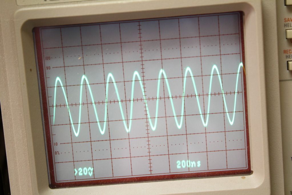 Here is the carrier at audio frequency 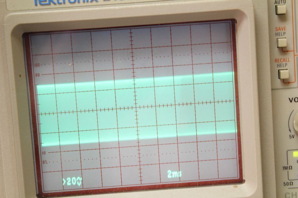 Modulated at what I think is 100% modulation - 600 Hz 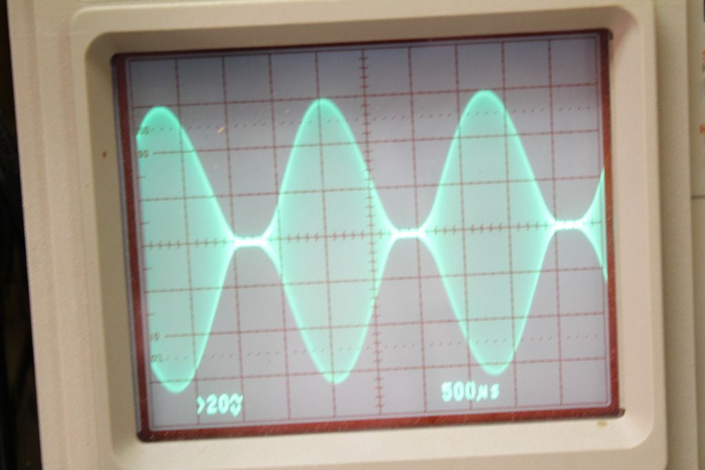 Same 600 Hz signal 150% overmodulated - I have lots more audio - can go twice this high probably. 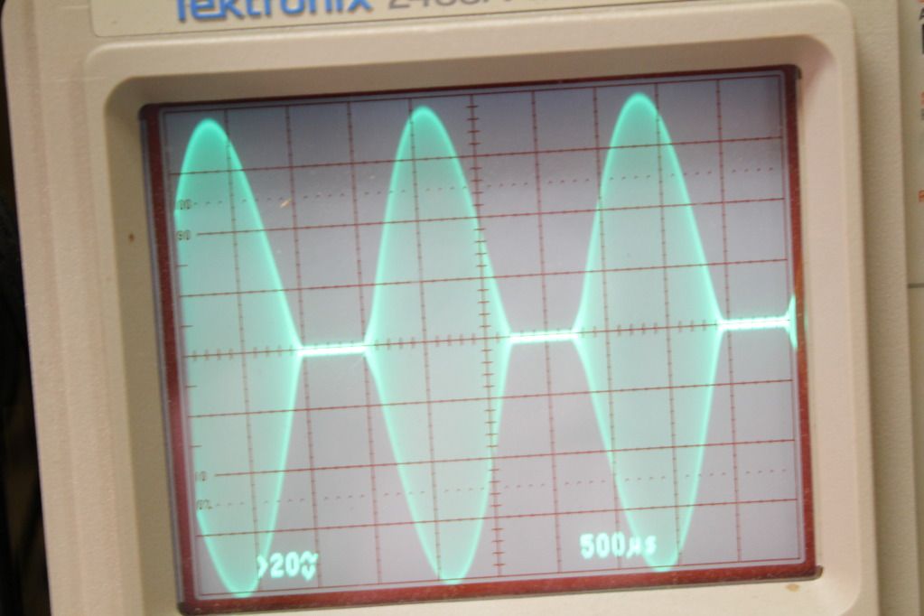 100% modulation at 6000 Hz 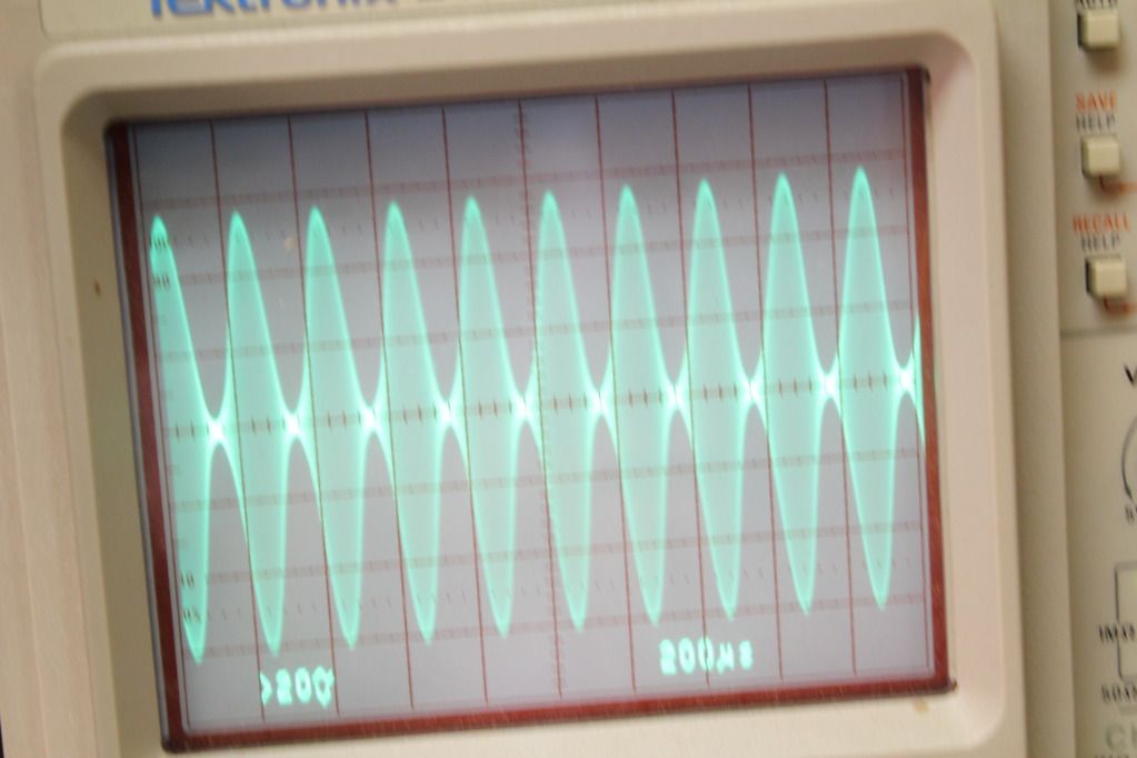 Here is 100Hz at what I think is 100% 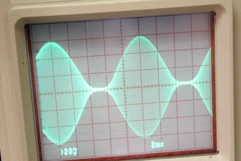 and here is 50 Hz at 100% 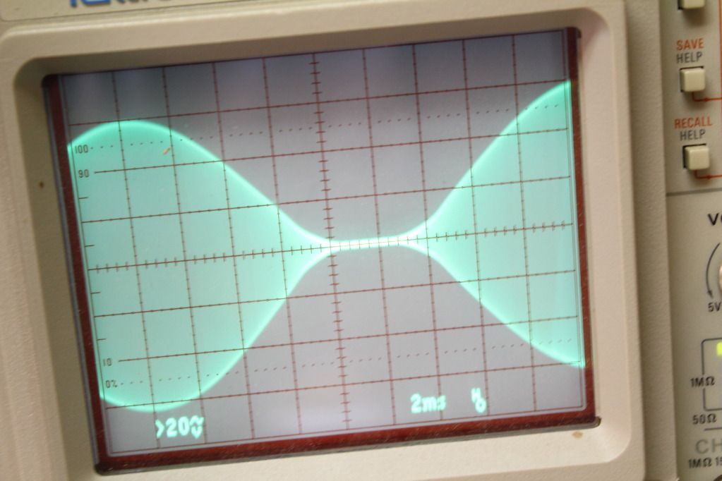 What the verdict - The 3 diode limiter keep alive control made some minor reduction of negative peaks when adjusted from 5-52 volts from the power supply. I believe the the pi net is close. This amp is operating at very low plate impedance less than 2000 - so figuring 8 H /1000 ohms - 15H may not be all that bad. It looks OK at 50 Hz to 6 Khz - I think? Pat N4LTA |
|
|
|
|
Logged
|
|
|
|
K5IIA
Member
Offline
Posts: 400
|
|
« Reply #6 on: March 26, 2012, 06:25:21 PM » |
|
Can you go any higher on the keep alive supply?
|
|
|
|
|
Logged
|
Be kind, for everyone you meet is fighting a hard battle.
73, Brandon K5iia
|
|
|
W7TFO
WTF-OVER in 7 land Dennis
Contributing
Member
Offline
Posts: 2525
IN A TRIODE NO ONE CAN HEAR YOUR SCREEN
|
|
« Reply #7 on: March 26, 2012, 06:43:16 PM » |
|
That flat line between peaks is overmod, sorry.
73DG
|
|
|
|
|
Logged
|
Just pacing the Farady cage...
|
|
|
N4LTA
Contributing
Member
Offline
Posts: 1075
|
|
« Reply #8 on: March 26, 2012, 07:05:44 PM » |
|
Yes - I can go to 90 volts with a resistor change. That would make the regulator disapate a little less
I ran the peak to 2 x the unmodulated carier to get a image of the negative peaks at 100 % positive modulation. All I have to do is turn the audio pot down a smidge to clear that up. I have enough power to go to 300% in the positive direction without heating up the modulation transformer.
Shouldn't the negative peak limiter crank down the negative peaks at over 100% positive?
Pat
N4LTA
|
|
|
|
|
Logged
|
|
|
|
K5IIA
Member
Offline
Posts: 400
|
|
« Reply #9 on: March 26, 2012, 07:12:27 PM » |
|
As you increase voltage you will see your negative mod be limited to less then 100 but it will still be flat topped. K1jj or some others can explain it better. I remember with mine I thought it didn't work. But I ended up using an isolation transformer and it provided enough dc after rectum fur cation.
|
|
|
|
|
Logged
|
Be kind, for everyone you meet is fighting a hard battle.
73, Brandon K5iia
|
|
|
|
Steve - K4HX
Guest
|
|
« Reply #10 on: March 26, 2012, 07:13:28 PM » |
|
Yes, it should, if operating and correctly adjusted. From the last scope photo something is not correct. Don't worry about modulating more than 150-200% positive. Most receivers won't deal with it, so you'll be loud but sound like crap.
Shouldn't the negative peak limiter crank down the negative peaks at over 100% positive?
|
|
|
|
|
Logged
|
|
|
|
N4LTA
Contributing
Member
Offline
Posts: 1075
|
|
« Reply #11 on: March 26, 2012, 07:31:14 PM » |
|
I am using Steve's (QIX) 3 diode limiter circuit with a keep alive power supply that can supply 5-52 volts.
The resistor is a 6 watt 2400 ohm and the diodes are rated 3000 volts at 2 amp (two 1500 volts 2 A diodes in series)
The transmitter with the modulator installed is running at 325volts at 150 mA - About 2200 ohms - the resistor was sized for the transmitter before the modulation choke voltage drop was figured in - but it is still pretty close.
The 3 diode limiter is installed with the Heising choke - although Steve showed it with a modulation transformer. The capacitor in the modified Heising circuit is a 6 uF oil filled rated 1000 volts AC
Pat
N4LTA
|
|
|
|
|
Logged
|
|
|
|
|
|
N4LTA
Contributing
Member
Offline
Posts: 1075
|
|
« Reply #13 on: March 26, 2012, 09:28:32 PM » |
|
I believe that the negative peak limiter is working. I can drive the modulation to 300% and more but I do not ever get the negative "reverse bump" shown in the above drawing. The more positive modulation that I add - just flats the negative area.
Still not sure what the waveform should look like with 150% positive modulation and the negative peakes limited to less than 100%
Pat
N4LTA
|
|
|
|
|
Logged
|
|
|
|
W7TFO
WTF-OVER in 7 land Dennis
Contributing
Member
Offline
Posts: 2525
IN A TRIODE NO ONE CAN HEAR YOUR SCREEN
|
|
« Reply #14 on: March 26, 2012, 10:09:19 PM » |
|
Try and not get caught up in the + peak frenzy.
Anything more than 110% is not going to go easy thru most detectors.
It produces 'listener fatigue', found out the hard way by countless BC buyers of crappily designed audio processors in the 80's & 90's.
The guys at RCA (and others) weren't ignorant when building AM transmitters that wouldn't do much + peak asymmetry. The bottom line was happy listeners, and programming quality not loudness kept them happy.
Flame suit on from those espousing high degrees of asymmetry today.
73DG
|
|
|
|
|
Logged
|
Just pacing the Farady cage...
|
|
|
K5IIA
Member
Offline
Posts: 400
|
|
« Reply #15 on: March 26, 2012, 10:34:25 PM » |
|
it will not look like that drawing. all you have to do is modulate it until you hit the base line. when you hit the base line it will just be the trace there. when you are like that increase the voltage of the keep alive supply until you see the line created by hitting the baseline increase in size.
like i said earlier it will still look ugly. but what the keep alive deal deos is keep some voltage there and stop the tube from shutting off and causing splatter.
but like i say there will be zero difference in how it looks down there around the baseline. all that you will do is have a thicker line in the middle.
i had the same questions when i did mine. and still dont understand it all the way.
if you crank your voltage all the way up on the keep alive supply and do not see the line in the middle where youa re hitting the baseline get thicker then either somethign is wrong, or like in my case it needed more voltage.
i figured how much voltage i would need from steve's wright up but i ended up needing a good bit more then what i came up with from the formula.
hope this helps some. and sorry for the misspelled words and lack of punctuation. southern schools ya know. haha
|
|
|
|
|
Logged
|
Be kind, for everyone you meet is fighting a hard battle.
73, Brandon K5iia
|
|
|
|
Steve - K4HX
Guest
|
|
« Reply #16 on: March 27, 2012, 12:16:37 AM » |
|
If the limiter was working you would not get a flat line in the center of your oscilloscope waveform. instead, the line would have some thickness depending on at what percent of negative modulation the limiter starts to limit. You can modulate way over 100 percent without any limiter (assuming the RF final is set up correctly and you have the modulation power). Don't be fooled by the big positive peaks and assume the limiter is working. The little bumps in QAA's post are not what you get when using a 3-diode limiter. You get the "bumps" when you use a balanced modulator. I believe that the negative peak limiter is working. I can drive the modulation to 300% and more but I do not ever get the negative "reverse bump" shown in the above drawing. The more positive modulation that I add - just flats the negative area.
Still not sure what the waveform should look like with 150% positive modulation and the negative peakes limited to less than 100%
Pat
N4LTA
|
|
|
|
|
Logged
|
|
|
|
Opcom
Patrick J. / KD5OEI
Contributing
Member
Offline
Posts: 8315
|
|
« Reply #17 on: March 27, 2012, 12:28:07 AM » |
|
If you have the limiter and keep alive built up but it is not working, check to see the diodes are in the right polarity. Silly but..
How about trying a high level of keep-alive for the initial tests and a lower value of series resistor, so you can be sure to very easily see the limitation of downward modulation that ought to be imposed. Then you can know it is working and adjust to the proper values. You are sure the keep-alive supply can supply enough current? Dumb questions sometimes shed light on come complicated corner of the thing in question.
|
|
|
|
|
Logged
|
Radio Candelstein - Flagship Station of the NRK Radio Network.
|
|
|
IN3IEX
Member
Offline
Posts: 128
|
|
« Reply #18 on: March 27, 2012, 04:27:12 AM » |
|
Excuse me if I am a bit out of the general consensus. First of all, by definition, undistorted AM CANNOT GO over 100% modulation. What follows is related to plate and screen modulation of a HF tetrode. My experience (that agrees with general knowledge) is that if you push modulation even a bit over 100% the transmitter produces wide band "splatter" up to VHF. I live very near another HAM and I know what happens next.... High level diode limiters are very efficient in reducing splatter, but a HF low pass filter is still recommended. High level diode limiters do not reduce distorsion. To keep modulation undistorted and below 100%, but still near 100%, an audio compressor is necessary, combined with a modulation meter. This is what most do. Consider that the audio adjustments depend on RF adjustments and are delicate.... That is why I think that an ALC can be a great operative advantage. Unfortunately an ALC normally requires a specifically designed integrated modulator. This is my conclusion. An example of a working and very simple ALC is here: http://amfone.net/Amforum/index.php?topic=30073.0If you can accept some solid state in your TX or want to use an external modulator, it could be interesting to "extract" a control signal from the diode limiter and send it to a "black box" to be inserted between the microphone and the external audio amplifier. The black box would be a VCA. As soon as the diode limiter starts limiting the control signal will reduce audio gain. You can decide the dynamics of the process, if it is very slow you simply get an automatic gain control with no modification of audio dynamics; if it is fast you have a compressor. The difference will be the value of a capacitance in the circuit and the possible use of a diode to have different attack and release time constants. I actually use a fast controller with symmetric attack and release times, therefore I have an audio compressor. Have fun with AM and invent new circuits !!. Giorgio More from another forum....: http://www.amforever.com/viewtopic.php?f=2&t=254&p=961&hilit=A+New+4+Diode+Negative+Peak+Limiter#p961 |
|
|
|
|
Logged
|
|
|
|
WD5JKO
Member
Offline
Posts: 1997
WD5JKO
|
|
« Reply #19 on: March 27, 2012, 07:44:23 AM » |
|
Pat, I concur with what Patrick says concerning getting the 3 diode limiter to work. I also agree with Georgio concerning the diode switching on/off causes transients, and bandwidth widens. There was a thread here where I spent considerable time going through variations of the three diode limiter, and I always followed the diodes with a low pass filter on the modulated B+ line. Unfortunately many a good thread here gets deleted entirely because of someones single inappropriate post. Fortunately this thread still survives: See reply 8 on this thread: http://amfone.net/Amforum/index.php?topic=22341.0 Here I ultra modulated a Viking I with a Crown M600 (750W RMS audio at 8 ohms). I used a Harmon Kardon Citation V audio output transformer as a step up modulation transformer along with a Heising choke and cap. I used a 4 diode circuit to progressively attenuate the negative cycle beginning when the first of three thresholds are met. Prior to that the audio passes through without alteration. I feel that this approach along with a LPF produces a much better sound then the hard limit of the 3 diode circuit, especially when the LPF is omitted. That hard limit at the keep alive threshold produces distortion products that widen the channel width. The circuit I used does "unload" the modulation transformer as opposed to the more typical negative cycle loading schemes. This is not a problem though when using a tightly coupled modulation transformer and a zero source impedance solid state modulator. I would not try this with a vacuum tube modulator though like with 807's. Jim WD5JKO |
|
|
|
|
Logged
|
|
|
|
IN3IEX
Member
Offline
Posts: 128
|
|
« Reply #20 on: March 27, 2012, 08:42:49 AM » |
|
Jim:
the progressive HV clipper looks very interesting and simple...maybe it is possible to reformulate it with a single 150V supply and voltage dividers?
See attached.
Giorgio
|
|
|
|
Logged
|
|
|
|
The Slab Bacon
Member
Offline
Posts: 3934
|
|
« Reply #21 on: March 27, 2012, 09:03:08 AM » |
|
Pat, Scope patterns all look pretty good excapt for the last one? ? I think that is just a sweep frequency mismatch on your scope. (sweep speed is a bit fast) I still wonder about using a 3-diode circuit with modified Heising modulation. It was really designed for a mod tranny without a reactor. Other than that.............. It looks pretty much textbook. Now................. Stop futzing with it, accept the fact that it is working, and get it on the air and use it! ! ! ! !  Ya done good, om. |
|
|
|
|
Logged
|
"No is not an answer and failure is not an option!"
|
|
|
N4LTA
Contributing
Member
Offline
Posts: 1075
|
|
« Reply #22 on: March 27, 2012, 09:11:06 AM » |
|
My keep alive uses a solid state adjustable voltage regulator that has 90 volts at the input. I used the guidlines on the AM window to set the limits - so I set it a little higher than suggested about 52 volts.
When I change the voltage - the baseline thickness changes . The regulator can supply something close to 20 mA at 50 volts.
I built this as a test rig to test different modulation schemes as aa precussor to building a dual 813 transmitter. The idea was to learn on something a little less expensive and less likely to burn a hole in my hand.
The idea seem to be working well as I am learning a lot.
Thanks for the discussion and help. Keep making comments and thanks.
Pat
N4LTA
|
|
|
|
|
Logged
|
|
|
|
N4LTA
Contributing
Member
Offline
Posts: 1075
|
|
« Reply #23 on: March 27, 2012, 09:18:55 AM » |
|
That last scope shot was made at 50 cycles and I had a hard time synching it that slow. That is why it looks weird. I probably should not have included it.
I'm going to spend a little time researching Jim's data. One of the things that held me back from AM was the lack of a decent modulation transformer and the Hammond SE transformer seems to be the trick. The 125GSE that I am using runs cold at 60-80 watts of audio (sine wave) after 30 minutes key down.
I asked Hammond if they would be interested in making one with a PP primary instead of the 4-8-16 ohm winding and was told a prototype would cost $700. Maybe I need to talk to someone else at Hammond.
Pat
N4LTA
|
|
|
|
|
Logged
|
|
|
|
KA3EKH
Member
Offline
Posts: 778
|
|
« Reply #24 on: March 27, 2012, 09:43:16 AM » |
|
Thought your waveforms look good, I always assume that you never want to be killing the carrier completely between peaks and would speculate that your underestimating your percentages by ten or fifteen percent. Maybe what your calling 100% is like 110% or so, dont think you ever want to cut the carrier off completely. Thought the diodes and all that stuff was going to prevent that? Try looking at the output with your spectrum analyzer. I have found that when things get overdriven or clipped they tend to produce wide band noise and thats always a good test to see how the transmitter is doing and also a excuse to see how you're doing on your second and third harmonic. Dont know what the rule is for homebuilt but think you are supposed to get 2nd and 3rd down at least 50 dB below carrier. I had a hell of a time getting my 2nd below 40 dB on the RCA transmitter I did and at 42 down am happy and ended up using one of those old Johnson TVI filters to knock all the spurious junk above 50 MHz below 60 dB.
What are you going to do for cabinets? Maybe put front panels and rack mount the power supply and transmitter? Also would think a big analog plate current meter would look good with that and maybe a third deck with a tube modulator too!
|
|
|
|
|
Logged
|
|
|
|
|


