Wayne WA1SSJ just completed a new 450 Watt (carrier) Pulse Width Modulator /Power Supply for his transmitter. Wayne completed the RF amplifier a few years ago. Wayne had been using an analog modulator (with the existing RF amplifier from a few years ago), but built this one because it is considerably more efficient and is a lead-in for a more powerful unit in the future.
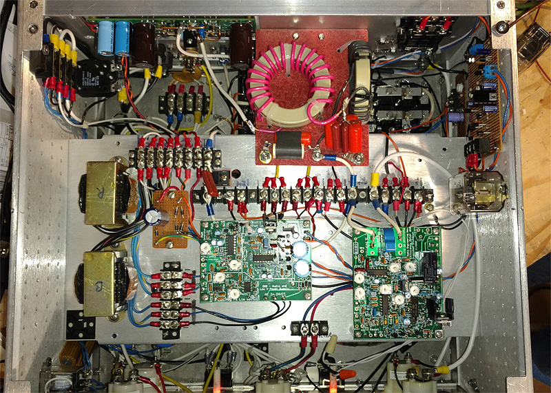
This modulator / power supply uses 3 IRFP260N MOSFETs in the modulator output section, mounted on a small heat sink.
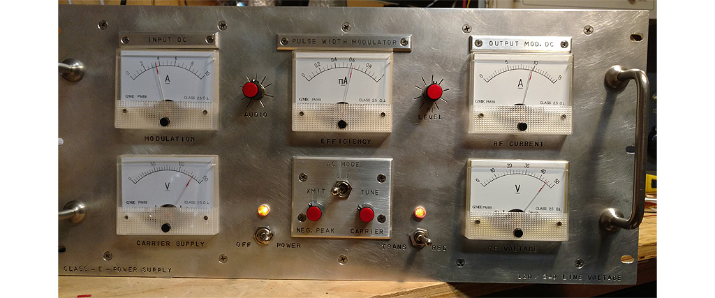
Wayne is a superb builder, and takes great care to properly lay out front panels as well as the internals (as the pictures show).
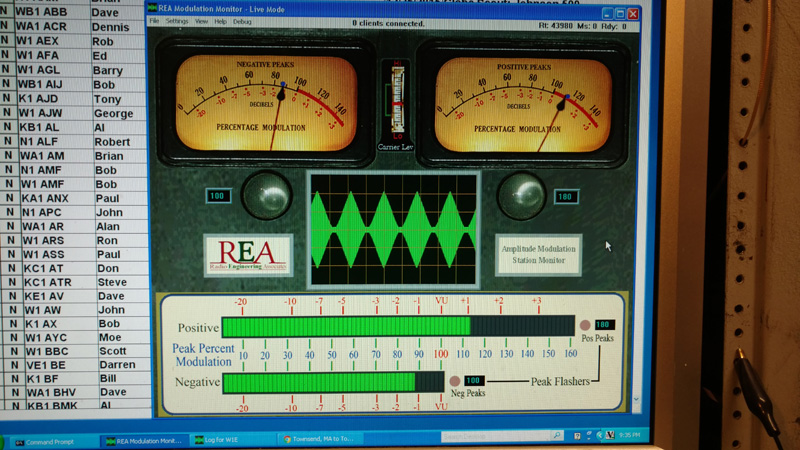
Also shown is the resulting modulation waveform of a 250 cycle triangle wave. The action of the negative peak limiter (set to around 90%) is clearly visible in the modulation display, as well as the perfect rendering of the triangular waveform in the modulation pattern.
Please excuse the poor pictures. I used my phone, and it's not too good with pictures unless you're outside in bright sunlight.
Here is the front of the modulator / power supply.
Here is the inside of the unit looking down. The PWM generator and Overload/Efficiency board are near the front, and the PWM filter and output are visible near the back.
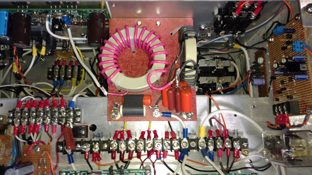
Here is a closeup of the PWM filter. Note the filter is constructed completely using cores, reducing the filter's size considerably. This can be done at the kW level as well.
Here is the resultant modulation display of the modulator modulating a 450 watt carrier class E RF deck with a triangle wave.