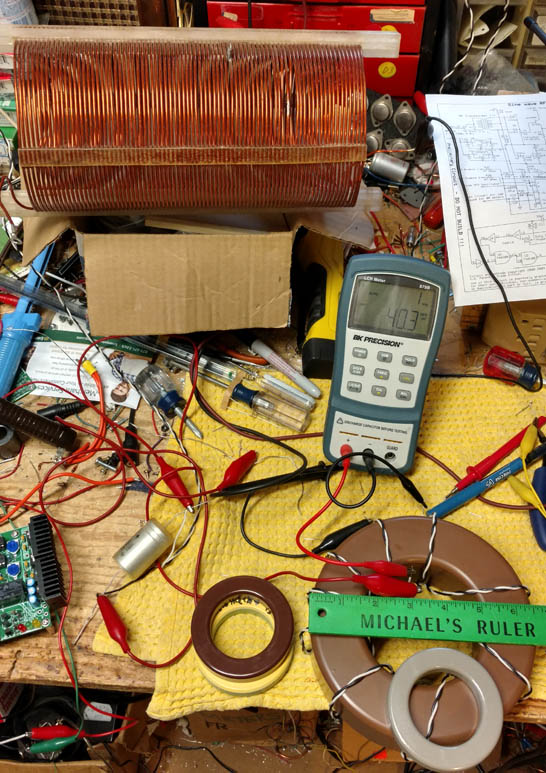
For a while now, I've been using toroids in PWM filters in pulse width modulators used to modulate class E transmitters.
The advantage of toroids over air wound coils is obvious - space. The DIS-advantage of cores is that the permeability changes with current, and this causes the value of the inductor to change with current - specifically, while modulating.
So, in order to have a successful inductor, the value of the inductor cannot change very much at all over the modulation cycle from max to 0 (100% negative).
There are good core materials that have very stable AL values (initial permeability) over a wide range of ampere-turns (DC bias) values.
I did some experiments with 4 different core materials - measuring the inductance of a single layer toroidal inductor with 0A of current and with 12 A of current flowing through the inductor itself. The findings are interesting, but not unexpected. The better the core material, the more stable the inductor.
Results:
| Core Description...................................... | Inductance No DC Bias.... | Inductance 12A DC Bias.... | Percent Inductance Change (drop) |
| . | | | |
| Micrometals T300-40 3.063 O.D. | 63uH | 53uH | 16% |
| Magnetics 58867A2 3.063 In. O.D.(Hi Flux) | 55uH | 54uH | 2% |
| Magnetics 78867A7 3.063 In. O.D.(X-Flux) | 53uH | 51uH | 4% |
| CWS CK1650060 6.5 In. O.D. (MegaFlux) | 40.3uH | 40.2uH | .25% |
The first three inductors are the same size, would on a "777" size core - about 3.063 inches diameter, and about 1/2 inch high. These are commonly available cores.
Obviously, the best (and of the most expensive) material is the Hi Flux. X-Flux is also quite acceptable, and is less expensive. The T300-40 core is UNACCEPTABLE as material for an inductor with varying DC bias. Micrometals does make a very good high flux core in the 777 size - I just don't have any of these here.
The CWS core is a _HUGE_ core, and it is VERY heavy. I have a bunch of these around, so I thought I'd measure it just for yuks. The Megaflux material is very similar to X-flux, and is acceptable for PWM filter inductors.
NOTE: Using a toroid as the
input inductor of a PWM filter is only acceptable for relatively low current applications (10A or under at carrier). The "Ripple Current" causes core heating and loss. I recommend using an air core inductor as the first inductor for anything over 10A. Stacking cores helps, but not much as the input inductor.
I have a 1kW pulse width modulator/power supply at Rattlesnake Island that uses a 6 pole filter (3 inductors). The first inductor is a small (in inductance) air wound inductor, and the remaining two are each made using 5 X-Flux cores stacked. This modulator delivers 26A of current at carrier, and the inductors are stable over the entire modulation capability of the system.
An inductance variation of 10% or less, over the entire modulation cycle is acceptable.
Micrometals and Magnetics both have very good inductor design software (free off their web sites), which will show you inductance variations, core losses, wire losses and other important data for their particular cores. I use this software all the time.
The Picture shows the three 777 size cores, one of which is setting atop the very large CK1650060 core. In the picture, the CK1650 core is the one wound at the moment. I wound the same wires around each of the smaller cores with the same number of turns for the experiment. The inductance differences between the inductors are the result of variations in the AL values of the different materials. The very large air inductor in the background is my "isolation" inductor, so I can make inductance measurements without the power supply "shorting out" the inductor during tests. The large air inductor is 350uH.


