Opcom
Patrick J. / KD5OEI
Contributing
Member

 Offline Offline
Posts: 8315

|
 |
« Reply #25 on: May 01, 2012, 10:45:41 PM » |
|
before canning it, have you put a 100 or 200 Ohm resistor in each screen lead? That is done in most audio amps with parallel 807's. A 50 ohm is put in the audio plate leads, but in RF the solution is for a suppressor.
|
|
|
|
 Logged
|
Radio Candelstein - Flagship Station of the NRK Radio Network.
|
|
|
The Slab Bacon
Member
Offline
Posts: 3934
|
|
« Reply #26 on: May 02, 2012, 08:11:55 AM » |
|
Makes me want to line all the 807s that I have up and get out the .22 .
You done been had   Save em for audio and other applications........... |
|
|
|
|
Logged
|
"No is not an answer and failure is not an option!"
|
|
|
N4LTA
Contributing
Member
Offline
Posts: 1075
|
|
« Reply #27 on: May 02, 2012, 08:44:33 AM » |
|
I have 47 ohm carbon comp resistors in each control grid and in each screen grid plus a 33 ohm in the cathode per RCA Tech notes plus a conventional parasitic suppressor in the plate leads.
I am wondering if a 6146 will drop in with a socket changeout and not have parasitic problems?
The transmitter has lots of work in it and I don't want to can it - though the power supply, bias supply, control relays etc are all on PC Boards and can be moved to a new chassis.
Pat
N4LTA
|
|
|
|
|
Logged
|
|
|
|
KC2ZFA
Member
Offline
Posts: 441
|
|
« Reply #28 on: May 02, 2012, 10:25:30 AM » |
|
Lower than fundamental frequency parasitics. Was a surprise to me.
They moved back and forth in frequency as the power slowly crept down and then back up.
Seemed to get worse as the transmitter warmed up. I could retune both the grid and the plate and stabilize it, but repeated keying brought it back and every now and then the parasitic frequency swept past the fundamental up to 7 or 8 Mhz.
this is fascinating ! have you tried a different driver ? |
|
|
|
|
Logged
|
|
|
|
WA1GFZ
Member
Offline
Posts: 11152
|
|
« Reply #29 on: May 02, 2012, 11:04:01 AM » |
|
Swap them out for a pair of 4D32s
|
|
|
|
|
Logged
|
|
|
|
|
W2ZE
Guest
|
|
« Reply #30 on: May 02, 2012, 11:27:54 AM » |
|
I have built an amp with 6l6gc's before and ran into the same problems with instability. I used link or inductive nuetralization to solve the problem. For more info, click here. http://www.vias.org/basicradio/basic_radio_28_04.html |
|
|
|
|
Logged
|
|
|
|
N4LTA
Contributing
Member
Offline
Posts: 1075
|
|
« Reply #31 on: May 02, 2012, 11:33:08 AM » |
|
Seems like I always end up with the fascinating stuff (unwanted fascinating stuff).
Was very strange - there were several frequencies - maybe 3-4 between zero hz and 3.7 hz slowly moving back and forth sometimes the group would move up to 7 mhz or so but mostly below 3.7 mhz. Would just pop up out of no where.
I'll put the driver on the sa tonite. It is a crystal oscillator driving a TC1413 mosfet driver which drives an IRF530A just like the Retro 75 with a relay keying it and a LM317 adjustable regulator feeding the IRF530 to give a drive level control. It works pretty well and it well filtered with a 7 pole filter at the output.
Pat
N4LTA
|
|
|
|
|
Logged
|
|
|
|
The Slab Bacon
Member
Offline
Posts: 3934
|
|
« Reply #32 on: May 02, 2012, 11:57:29 AM » |
|
The RCA notes say to bias the tube more into cutoff and drive it harder if you have instability. The tubes must have been buggers to design around.
I was just thiking about this. Since you are using some leaky grid biass, this means that you have to drive the tubes into class-C. Do you have enough drive available to drive them into class-C? ? ? ? ? If you have enough drive available you should notice the outpoot (or plate current) increase as you increase the drive to a point, then flatten out, then start to drop off as you continue increasing the drive. This is the point (along the plateau just this side of the drop-off) where you have driven the tube(s) into class-C. If you cannot do this, you do not have enough drive available to properly drive the tube(s). And/or drive them hard enough to get rid of the parasitics. Just a thought................. |
|
|
|
|
Logged
|
"No is not an answer and failure is not an option!"
|
|
|
WA1GFZ
Member
Offline
Posts: 11152
|
|
« Reply #33 on: May 02, 2012, 12:42:53 PM » |
|
My Dad loved 807s the best. I could take out the TV at will on 15m.
The TV antenna supported one end of my 15m dipole.
I switched to 6146s and never looked back. 807s better for audio.
|
|
|
|
|
Logged
|
|
|
|
N4LTA
Contributing
Member
Offline
Posts: 1075
|
|
« Reply #34 on: May 02, 2012, 01:51:29 PM » |
|
Slab,
Plenty of drive . Thats exactly what happens - increased drive increases output and plate current - then it flattens out and then drops as drive is increased. I have about 4 watts of drive max. It needs about 1 watt.
I finished the guitar amp and am going to play wiith it (or smash it) tonite. I got nailed by that guitar amp three times last night probing with one hand behind my back for a best heater ground - I gotta get some new glasses - one time it hurt.
I'm too careless with the lower voltage stuff I guess.
Pat
|
|
|
|
|
Logged
|
|
|
|
W3GMS
Contributing
Member
Offline
Posts: 3067
|
|
« Reply #35 on: May 02, 2012, 02:29:43 PM » |
|
Pat,
All indicators are that it needs to be neutralized. You have come this far with the 807's and I would not ditch them for your 80 M rig. Yes, other tubes may or are better, but many have been using 807's in a final for a long time. Just look through the older handbooks and you will find many good circuits. I built the one many years ago in the 1949 ARRL Handbook and it demonstrated very good stability all the way up to 10 meters. It used a pair of 807's.
Joe, GMS
|
|
|
|
|
Logged
|
Simplicity is the Elegance of Design---W3GMS
|
|
|
W7TFO
WTF-OVER in 7 land Dennis
Contributing
Member
Offline
Posts: 2525
IN A TRIODE NO ONE CAN HEAR YOUR SCREEN
|
|
« Reply #36 on: May 02, 2012, 02:50:08 PM » |
|
Pat,
Take a look at ARC-5 TX topology, they had if figured out at freqs higher than you are looking at.
73DG
|
|
|
|
|
Logged
|
Just pacing the Farady cage...
|
|
|
w7fox
Member
Offline
Posts: 102
|
|
« Reply #37 on: May 02, 2012, 03:07:20 PM » |
|
Pat,
I had a low freq. parasitic once. It was caused by having the same choke on the plate and the grid. Made a nice tuned plate tuned grid oscillator. Try changing one choke to some other value, or just a grid resistor if possible.
Best regards,
Chris
|
|
|
|
|
Logged
|
|
|
|
N4LTA
Contributing
Member
Offline
Posts: 1075
|
|
« Reply #38 on: May 02, 2012, 06:04:13 PM » |
|
Just hooked the driver to the SA - Don't think it is the problem. Here is a shot of the driver at 1.5 watts 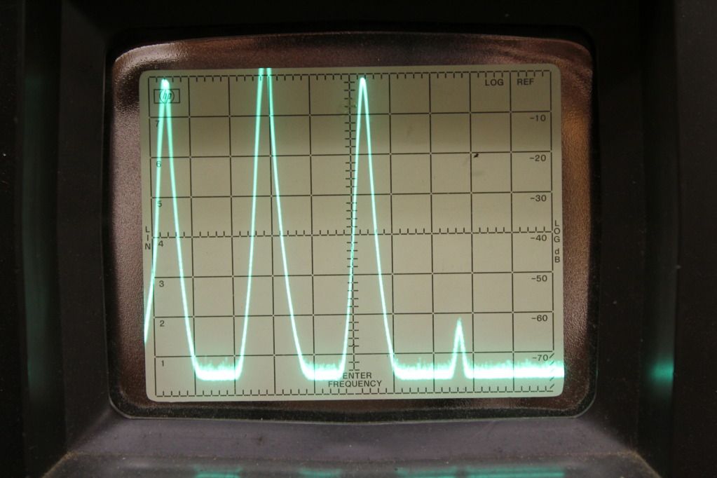 Here are a couple of photos of the driver - uses old FT243 crystals - keyey shorting the the RCA jack - runs on a Triad 18 volt 1 amp wall wart - variable from 0-about 4 watts out - looks like the second is down below 60dB 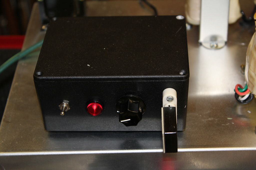 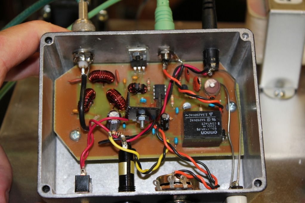 Don't ask why the corner of the board is cut off at the front. I'll keep looking Pat N4LTA |
|
|
|
|
Logged
|
|
|
|
KK4RF
Member
Offline
Posts: 158
|
|
« Reply #39 on: May 02, 2012, 07:18:52 PM » |
|
Pat,
I check at least twice a day now just to see if you've found the problem. This is becoming an epic struggle, better than any NCIS episode on TV.
Seems like it should work. I run an ARC-5 (BC-457A) on 80 meter cw and it is very stable. I have two old Globe Chief rigs with paralleled 807s in the amp circuit and they work through ten meters. Good luck and keep up the good work. ---Marty, KK4RF---
|
|
|
|
|
Logged
|
|
|
|
N4LTA
Contributing
Member
Offline
Posts: 1075
|
|
« Reply #40 on: May 02, 2012, 09:23:03 PM » |
|
Progress - I think I believe that most of the problem may be with an older variable cap in the grid circuit - but not sure I played around for about an hour tonite with the SA and scope hooked up. I found that the solid state driver didn't like loading the input transformer all that well so I put a 100 ohm resistor across the input (primary of the transformer) and removed a 10K across the secondary side that I had put there to reduce the input Q That seemed to help with the parasitic in that the parasitic only showed up when grid tuning was peaked and maximum drive (before power stopped increasing with drive) - If I slightly detuned the grid circuit and slightly lowered the drive - things were stable - but with long periods of "on" the grid circuit tuning changed and the power drops - but no parasitic and it looks thermal - like something is heating up and I suspect the cap in that high Q grid circuit. Anyway - I did a 15 minute old buzzard simulation at slightly reduced drive and a slightly mis-tuned grid circuit and I got the following: 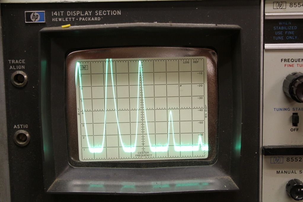  It feels like progress anyway Pat N4LTA |
|
|
|
|
Logged
|
|
|
|
ka1tdq
Member
Offline
Posts: 1509
Red part turned in for a refund.
|
|
« Reply #41 on: June 10, 2012, 12:19:10 PM » |
|
I had this exact same problem with my transmitter, which has a similar design. My configuration uses a grid tank with a 50 ohm link to an exciter. The transmitter uses a single 7984 tube for 15 watts out and is plate modulated.
I was using 1 watt of drive to the grid tank using a rice box and too had the problem of power dropping off to almost nothing and then slowly rising to maximum power in a few seconds. I experienced the problem during voice peaks, so I spoke softly into the microphone to avoid any cut-offs during my transmissions.
I was on the air with it and speaking to a ham in Maine (I forget his call, but God bless him!) and he told me that he too had the problem way back when and fixed it with more grid drive.
It was a quick fix for me! I kicked the Icom up an additional watt (now 2 watts of drive), hollered into the microphone and the problem was solved. I didn't notice any real change in grid current or power output.
I hope this helps.
Jon
KA1TDQ
Sent from my iPhone
|
|
|
|
|
Logged
|
Its not just values, its business.
|
|
|
w1vtp
Member
Offline
Posts: 2638
|
|
« Reply #42 on: June 10, 2012, 06:26:47 PM » |
|
Has anyone monitored the grid current of these 807 type transmiters? That is THE way of knowing if there is enough excitation. Two items that can destabilize a tetrode or pentode amp are:
1) Not enought grid drive (add improper bias to this combination)
2) Unwanted coupling from the grid circuit to the plate circuit.
We have yet to have a complete set of pictures of this amplifier to see if there might be a problem with the layout. 807 should not need neutralization at the frequencies we are discussing
Al
|
|
|
|
|
Logged
|
|
|
|
|


