KE7KPB
Member
 Offline Offline
Posts: 81

|
 |
« on: February 20, 2011, 09:47:31 AM » |
|
I would like to set up a scope to run on my station. What are the suggestions. I do own an IFR 1200s but that is used as a bench test equipment. I would like to fine a ww2 panadapter but what else could I use.
|
|
|
|
 Logged
|
|
|
|
w5omr
Member
Offline
Posts: 306
|
|
« Reply #1 on: February 20, 2011, 10:46:09 AM » |
|
I would like to set up a scope to run on my station. What are the suggestions. I do own an IFR 1200s but that is used as a bench test equipment. I would like to fine a ww2 panadapter but what else could I use.
Any ol' 'scope will work, for 160/75/40m... typicaly, a 20MHz scope can be found at a hamfest for less'n a C-note. Expect to pay a bit more for a 50MHz scope or higher. As far as getting RF into the scope, I've had luck by just slapping a BNC connector on one end of some RG-58 and fashioning a small little 2-turn 2"dia loop between the center and shield and placing it somewhere in the field of the transmitting antenna. |
|
|
|
|
Logged
|
|
|
|
|
Steve - K4HX
Guest
|
|
« Reply #2 on: February 20, 2011, 12:19:03 PM » |
|
Jeff is correct. Scopes are cheap these days. I got a 50 MHz B&K for $40 and a Tek 100 MHz for $75 at fests. Lots of good info on RF sampling for your scope in the thread below. http://amfone.net/Amforum/index.php?topic=26093.0 |
|
|
|
|
Logged
|
|
|
|
w3jn
Johnny Novice
Administrator
Member
Offline
Posts: 4619
|
|
« Reply #3 on: February 20, 2011, 01:52:13 PM » |
|
And see Geoff's signature for K4KYV's good reason for using a scope!
|
|
|
|
|
Logged
|
FCC: "The record is devoid of a demonstrated nexus between Morse code proficiency and on-the-air conduct."
|
|
|
KE7KPB
Member
Offline
Posts: 81
|
|
« Reply #4 on: February 20, 2011, 07:49:05 PM » |
|
I build a tuner last year so I am thinking I will incorporate an O scope sampling probe and build it in to the tuner. If it works than I will have a O scope BNC connector on the back of the tuner. The tuner was built on the T network with a 10 meter coil in the circuit. The tuner works great but I do wish I had built in a SWR meter into the circuit. But for now I tune for the loudest signal. I feel like a newbie to the am or the dark side of radio. The Philco Radio 38-7 is working great and I think the owner will be happy. Now I wish Winter would end. Next week - 20 degrees. Enough already.  Bob. |
|
|
|
|
Logged
|
|
|
|
KX5JT
Contributing
Member
 Offline
Posts: 1954
John-O-Phonic
|
|
« Reply #5 on: February 20, 2011, 08:38:11 PM » |
|
I have put a bnc connector on the back of a tuner housing and put a stiff wire from the center terminal into the tuner near the roller inductor. Worked fine business. Now my tuner is on a board and I just put the stiff wire from one phenolic end support to the other so it parallels the roller inductor by a 1/4 " or so. Also works fine business.
|
|
|
|
|
Logged
|
AMI#1684
|
|
|
w5omr
Member
Offline
Posts: 306
|
|
« Reply #6 on: February 20, 2011, 11:58:52 PM » |
|
I have put a bnc connector on the back of a tuner housing and put a stiff wire from the center terminal into the tuner near the roller inductor. Worked fine business. Now my tuner is on a board and I just put the stiff wire from one phenolic end support to the other so it parallels the roller inductor by a 1/4 " or so. Also works fine business.
I'd be careful as to how much RF you couple into the front-end of the scope, that way. I guess as long as you're not running a kW, you should be ok, but there's a limit as to how much RMS voltage a 'scope can take. |
|
|
|
|
Logged
|
|
|
|
KX5JT
Contributing
Member
Offline
Posts: 1954
John-O-Phonic
|
|
« Reply #7 on: February 21, 2011, 12:22:48 AM » |
|
I have put a bnc connector on the back of a tuner housing and put a stiff wire from the center terminal into the tuner near the roller inductor. Worked fine business. Now my tuner is on a board and I just put the stiff wire from one phenolic end support to the other so it parallels the roller inductor by a 1/4 " or so. Also works fine business.
I'd be careful as to how much RF you couple into the front-end of the scope, that way. I guess as long as you're not running a kW, you should be ok, but there's a limit as to how much RMS voltage a 'scope can take. Sometimes we gotta blow em up to learn. But thanks Geoff, I'd rather learn without losing the stuff. |
|
|
|
|
Logged
|
AMI#1684
|
|
|
KA2DZT
Member
Offline
Posts: 2192
|
|
« Reply #8 on: February 21, 2011, 01:27:25 AM » |
|
I use an old HP 1/2 meg scope. I feed the RF onto the vertical plates of the CRT. The plates are good to about 80 megs.
I had to modify the scope to do this. Some old scopes already have terminals to connect to the plates.
Fred
|
|
|
|
|
Logged
|
|
|
|
|
K1DEU
Guest
|
|
« Reply #9 on: February 21, 2011, 03:46:42 AM » |
|
Ah Hem, Fred I often wondered where the majority of your RF was going (or is it only about 1/2 a watt). Wow a balanced load. Twinlead ?
Definitely miss teasing you on 75. I always enjoyed the Heathkit monitor scopes allowing one to view the RF signal on transmit then the Received IF pattern of others transmitting. Always found long term problems in their weak HV supply.
The Kenwood line of monitor scopes (SM-220) are much more expensive but have a much better HV supply. John, K1DEU
|
|
|
|
|
Logged
|
|
|
|
w5omr
Member
Offline
Posts: 306
|
|
« Reply #10 on: February 21, 2011, 08:54:23 AM » |
|
The Kenwood line of monitor scopes (SM-220) are much more expensive but have a much better HV supply. John, K1DEU
Most receivers have an I.F. output and is usually a BNC connector. If the receiver is muted during transmit, you could set the trigger level on one channel to come up when the transmitter is actually on the air, and then on the other channel, set the trigger level to kick on with the appropriate signal level at the I.F. stage of the receiver. Ass/u/me'ing, of course, you've got a dual-channel scope ;-) |
|
|
|
|
Logged
|
|
|
|
KX5JT
Contributing
Member
Offline
Posts: 1954
John-O-Phonic
|
|
« Reply #11 on: February 21, 2011, 09:15:39 AM » |
|
And if your vintage boatanchor receiver does not have an IF tap and does have a 455khz IF.... ... the following device looks pretty interesting... http://www.electronicspecialtyproducts.com/interface.html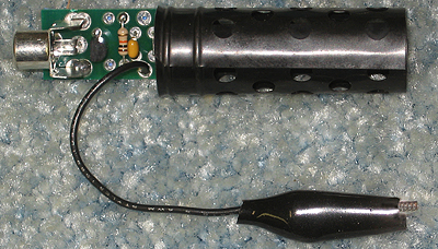 |
|
|
|
|
Logged
|
AMI#1684
|
|
|
KE7KPB
Member
Offline
Posts: 81
|
|
« Reply #12 on: February 26, 2011, 09:04:11 AM » |
|
How hard would it be to build a swr meter into a already built tuner? I was thinking about pulling the guts out of a store built and mounting it in my home brew tuner.
|
|
|
|
|
Logged
|
|
|
|
w3jn
Johnny Novice
Administrator
Member
Offline
Posts: 4619
|
|
« Reply #13 on: February 26, 2011, 09:52:20 AM » |
|
Been done many times. Some older SWR meters have a separate meters and directional couplers, and you can just re-mount the meter and place the coupler where ever you need it.
|
|
|
|
|
Logged
|
FCC: "The record is devoid of a demonstrated nexus between Morse code proficiency and on-the-air conduct."
|
|
|
W3SLK
Member
Offline
Posts: 2660
Just another member member.
|
|
« Reply #14 on: February 26, 2011, 10:33:53 AM » |
|
John said: Some older SWR meters have a separate meters and directional couplers, and you can just re-mount the meter and place the coupler where ever you need it. Yep! People don't realize that the Heathkit HM-15 has a removable measuring element with an umbilical cable to it. Makes it nice for placing the meter one place and the measuring element in another. |
|
|
|
|
Logged
|
Mike(y)/W3SLK
Invisible airwaves crackle with life, bright antenna bristle with the energy. Emotional feedback, on timeless wavelength, bearing a gift beyond lights, almost free.... Spirit of Radio/Rush
|
|
|
w5omr
Member
Offline
Posts: 306
|
|
« Reply #15 on: February 26, 2011, 02:04:52 PM » |
|
John said: Some older SWR meters have a separate meters and directional couplers, and you can just re-mount the meter and place the coupler where ever you need it. Yep! People don't realize that the Heathkit HM-15 has a removable measuring element with an umbilical cable to it. Makes it nice for placing the meter one place and the measuring element in another. That's a great meter. Takes abuse, too. I've had an HM-15 on the dash of my truck for Hundreds of thousands of miles. Still works. Recently replaced it in favor of a larger Daiwa cross-needle meter. Meter is ~6" tall, and fits perfectly in the in-dash 'tray' in my '06 F-150. |
|
|
|
Logged
|
|
|
|
w5omr
Member
Offline
Posts: 306
|
|
« Reply #16 on: February 26, 2011, 02:07:14 PM » |
|
That's a great meter. Takes abuse, too. I've had an HM-15 on the dash of my truck for Hundreds of thousands of miles. Still works. Recently replaced it in favor of a larger Daiwa cross-needle meter. Meter is ~6" tall, and fits perfectly in the in-dash 'tray' in my '06 F-150.
That's on the 1kW scale, on 75m, probably, displaying the maximum power of the amplifier output, with that amount of SWR. Meter is reading 700w. |
|
|
|
|
Logged
|
|
|
|
KE7KPB
Member
Offline
Posts: 81
|
|
« Reply #17 on: February 27, 2011, 04:02:45 PM » |
|
Update:
Installed a SWR meter assembly and a weird thing is happening, When I start the to tune the tuner for the lowest SWR, it actually tunes backwards on the meter. So for the lowest SWR, I need to tune for the highest SWR. Other than that it does work.
|
|
|
|
Logged
|
|
|
|
|
Steve - K4HX
Guest
|
|
« Reply #18 on: February 27, 2011, 06:29:33 PM » |
|
Reverse the leads on the meter?
|
|
|
|
|
Logged
|
|
|
|
Opcom
Patrick J. / KD5OEI
Contributing
Member
Offline
Posts: 8315
|
|
« Reply #19 on: February 27, 2011, 08:28:41 PM » |
|
Update:
Installed a SWR meter assembly and a weird thing is happening, When I start the to tune the tuner for the lowest SWR, it actually tunes backwards on the meter. So for the lowest SWR, I need to tune for the highest SWR. Other than that it does work.
could be a ground issue with the coupler or the in and out have been reversed or the switch (wiring) positions reversed. |
|
|
|
|
Logged
|
Radio Candelstein - Flagship Station of the NRK Radio Network.
|
|
|
KM1H
Contributing
Member
Offline
Posts: 3519
|
|
« Reply #20 on: March 03, 2011, 12:12:13 PM » |
|
Im using the SM-220 on the TS-940 and 950SD and a freebie 1946 5" Dumont on one of the BA benches. Picked up a freebie rack mount 5" Fairchild for another bench but its not been recapped yet.
I have used the Tek 453 to setup the Clegg Zeus on 6M, its easier to move around.
Carl
|
|
|
|
|
Logged
|
|
|
|
KD6VXI
Contributing
Member
Offline
Posts: 2652
Making AM GREAT Again!
|
|
« Reply #21 on: March 04, 2011, 12:19:35 PM » |
|
I've got the HM-102 Heathkit meter, and it's the same: Has an umbilical cord.
As to it tuning backwards, you've probably reversed the leads to the meter, or the switch, when you where wiring it back together.
My Yeasu YS-60 is also remoteable. When Radio Shack phased out that digital wattmeter / swr combo in 98 or 99, I found one sitting on a shelf for 19 dollars in Ponca City, Ok.... SNAPPED that up, makes a GREAT remote unit for remote tuna'ing... Auto computes SWR, and is about 10-12 percent in agreement with the 43 in avg mode.
--Shane
KD6VXI
|
|
|
|
|
Logged
|
|
|
|
WA1HZK
Member
Offline
Posts: 1104
|
|
« Reply #22 on: March 06, 2011, 03:09:06 PM » |
|
I use a cheap 20 MHZ dual trace here and could not be without it. It's the only way to tune a boat anchor for non crappy audio. You need to go in and tap the IF string for signal. a 5-10 pf. silver mica will do this. make a connection off of the plate of one of the IF tubes to your connector. Use mino coax to run to the connector. Just experiment a little and route it to an RCA jack on the back of the rcvr. (Watch the 300 volts, it bites) For the transmitter don't overlook that Low Pass filter you have in line. Mount a RCA or BNC on it and make a loop, 3-4 turns about 1" in dia around the connection to the input or output SO239 connector on the filter. Run a piece of Coax right to the scope from your loop. If the signal looks funky add a 3 mh RF choke across the scope input to get rid of the audio. You only want RF here. Once you have this running you will wonder how you ever operated without it. PS, you can also demodulate the RF from your Low Pass pickup and feed it to headphones to get a feel for what you actually sound like. That's also covered in the TX notes on this site I'm pretty sure.
Keith
WA1HZK
|
|
|
|
|
Logged
|
|
|
|
|


