The AM Forum
May 01, 2024, 10:56:14 PM *
Welcome, Guest. Please login or register.

Login with username, password and session length
 
   Home   Help Calendar Links Staff List Gallery Login Register  
Pages: 1 [2]   Go Down
  Print  
Author Topic: AB Standard Receiver  (Read 11521 times)
0 Members and 1 Guest are viewing this topic.
K1JJ
Contributing
Member
*
Offline Offline

Posts: 8893


"Let's go kayaking, Tommy!" - Yaz


« Reply #25 on: August 31, 2014, 11:21:20 AM »

Thinking it was lightning. Untill I saw something else. On the back of the unit right behind the wave form selector is 2 binding post, red and black. These are the antenna connection. The adjustment would not turn. So I opened it up and found a lot of wax in the varible capacitor. It is possible that someone thought these were to connect a battery or power supply to. And would had sent all that power straight to the band board.


I can see it now.  It's 1984 and an excited Johnny Novice gets his first receiver for $10. No manual.  He connects his Asstron 13.8V power supply to the red and black posts.  Excitement turns to despair in 100 milliseconds.  

I've been there.   Grin

T
Logged

Use an "AM Courtesy Filter" to limit transmit audio bandwidth  +-4.5 KHz, +-6.0 KHz or +-8.0 KHz when needed.  Easily done in DSP.

Wise Words : "I'm as old as I've ever been... and I'm as young as I'll ever be."

There's nothing like an old dog.
kc4umo
Member

Offline Offline

Posts: 200


WWW
« Reply #26 on: August 31, 2014, 12:07:34 PM »


I can see it now.  It's 1984 and an excited Johnny Novice gets his first receiver for $10. No manual.  He connects his Asstron 13.8V power supply to the red and black posts.  Excitement turns to despair in 100 milliseconds.  

I've been there.   Grin

T

Beautiful analogy of what may have happened.  And you are most likely correct. I can see that clear as day.

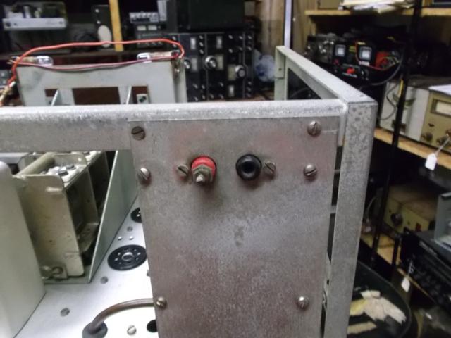
Hey, these are red and black right? Power surely connects here.


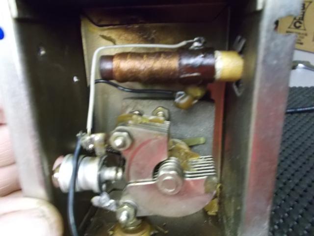
Now that is not right. All the wax melted off the coil and dripped into the capacitor.
The coil checks as a resistor now at .7 ohms.


So where did the power go from here?


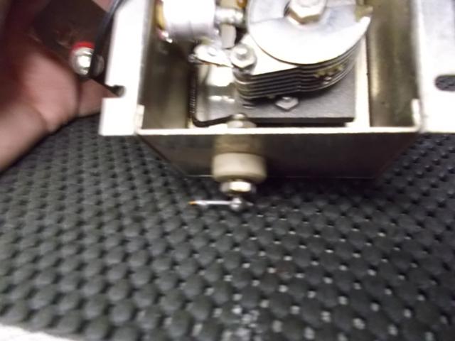
And right smack dab into the fried coil


Oh well, just more to fix…….
Logged

kc4umo
Member

Offline Offline

Posts: 200


WWW
« Reply #27 on: August 31, 2014, 04:57:53 PM »

The antenna wavetrap repaired.

As far as the fried coil, let it be. I cleaned it up, removed all traces of carbon. The coil is still intact and should function as long as it does not need adjusting. So will cross that bridge later. Next is to start the repinting of the cabinet and front panel, then tackle the name plates.  Then recap the unit and start looking at tracing all the circuits to build a power supply.

In the mean time I am going back to the TX-1 for rest of the day and tomorrow.
Sounds like a plan to me....
Logged

Pages: 1 [2]   Go Up
  Print  
 
Jump to:  

AMfone - Dedicated to Amplitude Modulation on the Amateur Radio Bands
 AMfone © 2001-2015
Powered by SMF 1.1.21 | SMF © 2015, Simple Machines
Page created in 0.052 seconds with 18 queries.