Well, I finally got the modulator together, and it's working perfectly. Came right up the first time - no issues, but before bringing anything up I tested every sub-system first to verify proper operation.
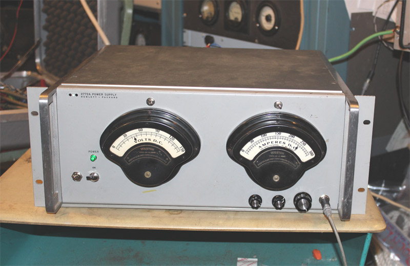
The compact "AM Killowatt" modulator/power supply fits in a 7 inch enclosure that used to be an H.P. power supply of some sort. I never had the inside - got the cabinet empty, so I don't know exactly what was there. The cabinet is the perfect size for the Pulse Width Modulator/power supply combination.
The current meter reads 1/10 of the value shown (obviously, I'm not running 200 amps of current!!). I've had those vintage meters for a long time, and this is a great application. The volt meter is correct. Both meters can be switched between monitoring the output voltage and current (supplied to the RF amplifier) and monitoring the input (supplied to the pulse width modulator) voltage and current.
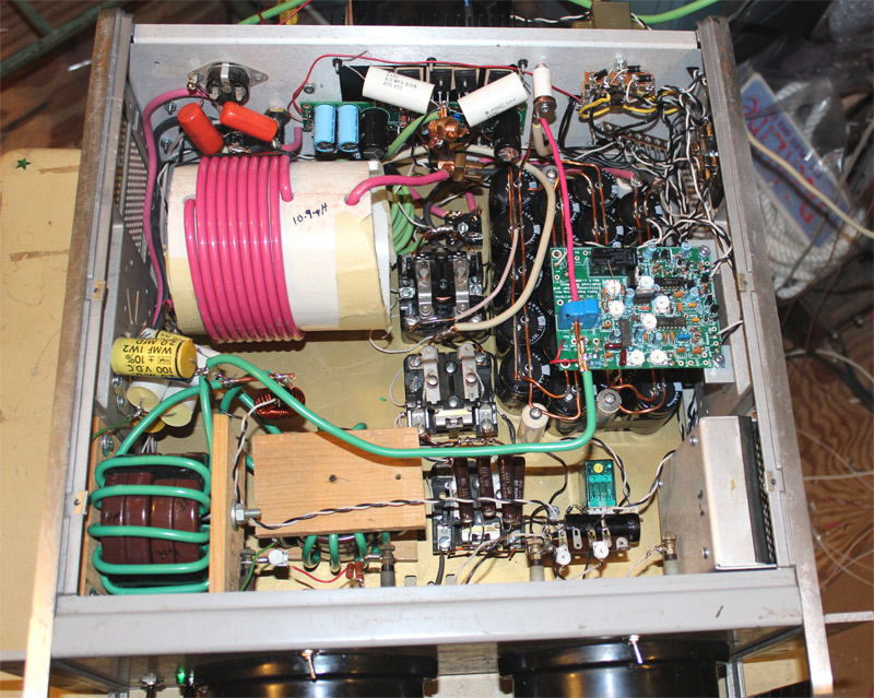
This modulator uses toroids in 2 of the 3 inductors in the PWM filter, greatly reducing the filter size. The input coil is an air core coil (10.9uH), and the 2nd and 3rd coils are toroidal - 43uH and 30uH respectively. Each toroidal inductor uses 4 X-Flux cores stacked, in order to handle the peak current. In reality, a single core would actually have worked, but the inductance variation caused by the change in the AL value due to the current variations (with modulation) would have been excessive, and the filter would not be effective. With 4 cores stacked, there is very little variation in the AL value. These cores are not expensive (about $9.00 each), so stacking is not a big financial hardship.
The filter capacitor bank can be seen under the overload/shutdown board. This bank is made up from 20 2200uF 160 volt capacitors in parallel.
The PWM generator board is behind the metal shield, in the right-front corner. The PWM output board (5 MOSFETs) is mounted to the back of the enclosure, on a 6 x 6 heat sink.
There are several large relays in the center of the cabinet. These are the keying relays for the power supply, including the step start. The power transformer (a Signal DU-1) is external, and sits on the floor behind the modulator. The DU-1 weighs more than the entire modulator, and may in fact weigh more than both the RF amplifier and modulator combined! I should weigh the units and the transformer to see!!

A single wire runs through the current transducer in the overload shutdown board, from the output of the PWM filter and on to the RF amplifier.
Although the modulator is not particularly complex, it took a long time to build - much longer than the RF amplifier, so that the result would be a reasonably neat layout.
This transmitter is slated to go to Rattlesnake Island, mostly to improve the signal on 160 meters on those nights when I am net control of the Grey Hair Net. The rig covers 75 and 160 meters.