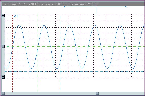
Applying the 99+% modulated signal and using the precision rectifier results in the following waveform:
Precision Detector 99+% Modulation
This waveform displays virtually no distortion not only visually, but also audibly. A pure tone is heard coming from the speaker. Actual on air comparative listening tests of 75 meter AM signals at levels from just over the noise to well over S9 were quite conclusive. Low level signals could be more easily heard through the noise, and high level signals we noticeably clearer.
Comments: Purists may want to use LM318 op-amps for all three stages, but I found no significant improvement when doing same at 50 KHz. I wanted to pick parts that were readily available and in particular in DIP packages so that any builder would be able to build up the circuit on a perf board, preferably the type with a ground plane on one side. This circuit is so stable at 50 KHz, that it was actually built and tested using a prototyping board with no ground plane at all. Operation at 455 KHz will definitely require a ground plane in the construction. At 455 KHz IF frequency and higher, the combining circuitry requires the use of three LM318's or equivalent.
The Math Behind The Detection Process.
There have been several articles written discussing the production of harmonic distortion by diode envelope detectors. Almost all of these start with the exponential diode equation and then examine the cross modulation products derived from the series expansion of the exponential function.
eX
= 1 + X + ½ X2+ 1/6X3 + 1/24 X4 +......The simplistic AM modulated signal is:
V(t) = A cos(Wc) t * [ 1 + B cos (Wm) t ], which expanded is;
V(t) = A cos(Wc) t + ½ AB cos(Wc - Wm) t + ½ AB cos( Wc + Wm) t
= Carrier + LSB + USB
Where, A is carrier peak voltage, B less than A, is peak modulating voltage, Wc is 2 *
P * Carrier Frequency, and Wm is 2 * P * Modulation Frequency. This is called simplistic because it is a model of the signal, not the generation process. This equation has no provision to deal with the case where B might be greater than A, as in over modulation.The term of significance here is the square term as it provides the cross product of the carrier with each sideband, as in synchronous detection. Unfortunately, it also provides the cross product of the two sidebands which produces second harmonic distortion of the modulating signal. These detectors are often referred to as square law detectors for this reason.
And, if you go through all the math you will get a term that represents some 25% second harmonic distortion, which is much more than what is usually experienced in the real world.
In the real world, diode detectors work into a load resistor which often has a parallel "filter" capacitor. If the diode were an ideal device, it would only allow current to flow in the load resistor during precisely one half of the input waveform. The resultant voltage developed across the resistor would then be precisely the half wave rectified voltage of the input signal. The reality is that the current/voltage relation in a diode is a non linear, exponential function as has been discussed. This means that the output voltage on that resistor would be the half waveform of the input signal minus the voltage across the diode.
Vout = Vin - Vdiode
It is the voltage across the diode that is the non-linear portion of the output signal, which becomes dominant at low input levels, such as the modulation trough of an AM signal. There are techniques that have been employed to reduce the diode component of the output waveform. One is to drive the detector into a high impedance load resistor. With the current very low, the voltage produced on the diode will be low. This approach is limited by the generally ignored reverse current of the diode. At high impedance levels, the rectifying function of the diode becomes compromised by the reverse leakage current, resulting in other performance problems.
The precision rectifier uses the features of op-amp feedback design to eliminate the diode error from the rectification process, resulting in a "perfect" rectifier. Well, why does a perfect rectifier work as a detector anyway? Most diode detector discussions talk about the square law function as discussed above to explain the demodulation process. The received carrier multiplies against the received sidebands. This is where the error comes in the thinking that it also should produce an objectionable level of second harmonic distortion. Let’s go back to the pure half wave rectified signal that the precision detector produces and the diode with the load resistor tries to emulate. What is the process that takes an input signal at some frequency, Wc, and outputs only the positive half of the waveform. It is just as if the signal were multiplied by one during the positive half cycle, and zero during the negative half cycle. The type of waveform to do this would be a square wave, with a values of one or zero, and at the same frequency and phase as the incoming carrier. The mathematical representation of a square wave is what is known as a Fourier Series expansion. For our sequence of one, zero, one, zero... at a frequency of Wc the function is:
f(X) = ½ + 2/
P cos Wc t + 2/3Pcos 3Wc t + 2/5P cos 5Wc t + ......When this is multiplied times the incoming signal, we get a result that is the half wave rectified waveform. Our interest is in the fundamental term, cos Wc t. The higher frequency harmonic terms and the DC term will produce results that are all at or above the incoming IF frequency. So the product term of interest becomes:
Vout(t) = {A cos(Wc) t + ½ AB cos(Wc - Wm) t + ½ AB cos( Wc + Wm) t} * 2/
P cos Wc tThe demodulated sideband terms are:
Vout(ty) = AB/2
P * cos(Wm) t + AB/2P * cos(Wm) t , orVout(ty) = AB/
P * cos(Wm) tThere are no intermodulation terms to contend with. IN fact, functionaly, this is identical to synchronous detection. The negative half wave signal is derived in a similar fashion. The two signals, when combined in the summing circuit produce an output with twice the ripple frequency to be filtered by an output low pass filter. This is of value when the IF frequency is only 50 KHz, as in the Drake R4-C and others. For receivers with a 455 KHz or 500 KHz IF, replace the two LCMC660 op amps with a pair of LM318's.