During the negative half of the input AC waveform, the op-amp output will drive positive such that the current through R2+D1 will be equal and opposite the input current, or:
Iin = Vin/R1 = -ID1 = -IR2
The voltage developed across R2, and hence the output voltage as the left side of R2 is at ground potential, will be:
V = Vout = -IR2 * R2 = -Vin/R1 * R2
By setting R1 = R2, the output voltage will be;
Vout = Vin
Similarly, the positive going input cycle produces a feedback current through D2. Any non linear voltages developed across the diodes is not relevant as the output is derived from the feedback resistor only.
A full wave detector was desired for a 50 KHz IF application so that the ripple frequency out of the detector would be 100 KHz, and more easily filtered. In the full wave detector version of the circuit, a second feedback resistor is added to the D2 diode path to produce a voltage of the other half of the input waveform. A virtual ground at +6 Volts was created with R814/R815/C812, so that the circuit could operate from a single supply. Again, any non linear voltages developed across the diodes are not relevant. The two rectified half waves are combined in the next two op-amp stages. The two outputs of the rectifier are connected directly to the non-inverting inputs of the op-amp stages so that there will no external loading to the outputs. U6B provides a gain of two to the signal voltage on R813. U6A provides a gain of two to the voltage on R811, and inverts and adds the output of U6B. The result is a full wave rectified signal at the output of U6A. Simple low pass filtering will remove the carrier energy which is at twice the ripple frequency.
The ability of this circuit to accurately track the input waveform is dependant on the speed of the op-amp and the switching speed of the diodes. For the circuit to track the input, the op-amp must be considerably faster than the input frequency. The LM318 with its 15 MHz bandwidth was selected for this reason and because it is readily available and stable. This circuit was built up and set up for comparison with the stock envelope detector in a Drake R4-C with a 50 KHz I.F. A HP8640 signal generator was used to provide a 1Khz modulated carrier at 3.885 MHz which was input to the antenna connector. The input level was set to S9 (30 uV). The detectors were compared at modulation levels of 80% and 99+ %. A Link Inc. , PC based oscilloscope was used to record and display the resulting waveforms.
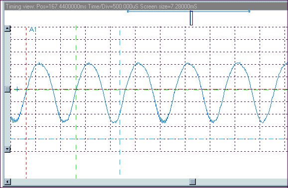
R4-C Stock Detector at 99+%
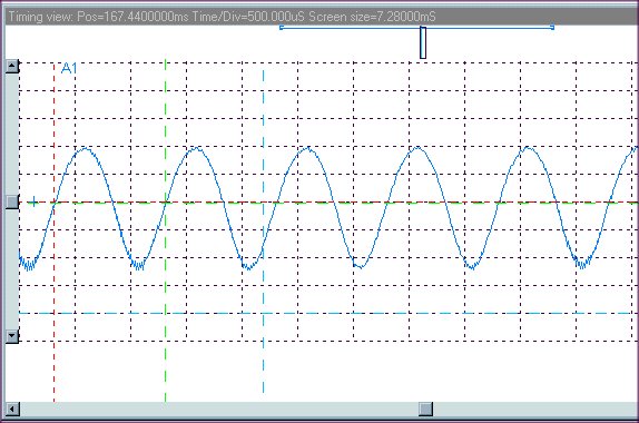
R4-C Stock Detector at 80%
 Click on image to enlarge
The distortion is visible at the crest of the wave, where the input signal is at the modulation trough in this inverting detector. The distortion at 80% is less visible than at 99+%, but still audible.