High Voltage Power Supply
Click the image to enlarge
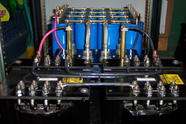
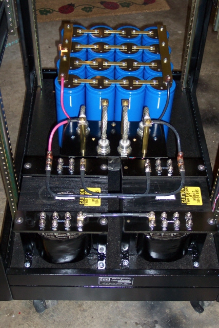
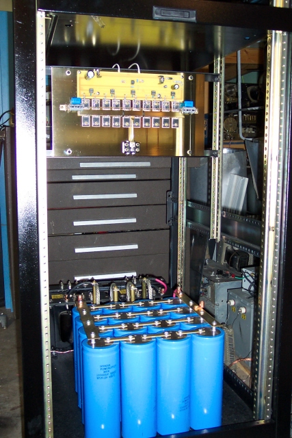
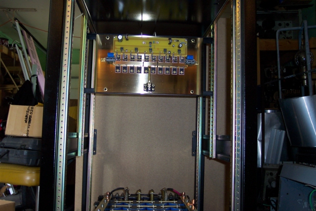
A shot looking through the rig from back towards the front.
Bridge rectifier rated 250 amps @ 600vdc
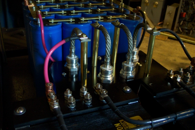
A pair of Signal Transformer DU2's rated at 2KVA each in parallel, rectified by the bridge rectifier and filtered with a 100,000 mfd @ 200v capacitor bank.
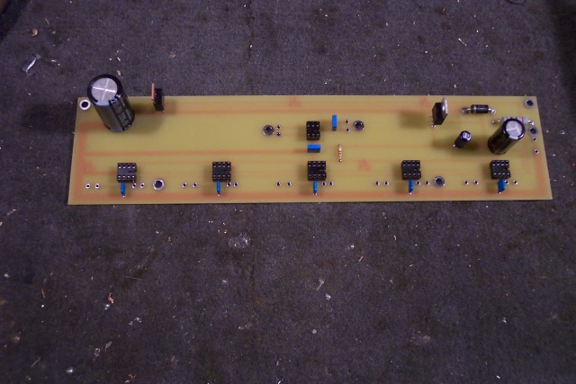
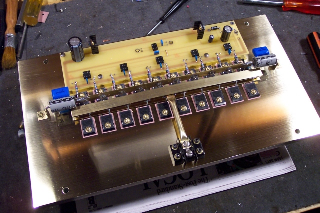
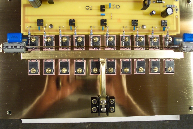
10 FET Pulse Width Modulator
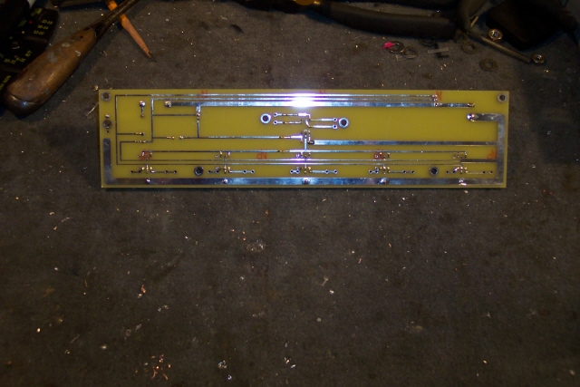
Fet Driver board
The FET Driver circuit was designed by Steve WA1QIX. I designed the layout for the board and had Express PC make the boards. I am very happy with the quality of the boards. Everything lined up and the holes were perfect.
The board will drive up to 10 FET's
Fet Driver board
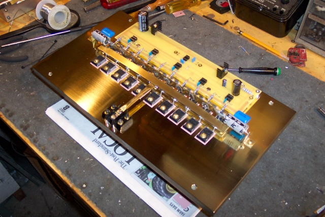
The modulator is built on a piece of brass that is .675" thick and weighs in at 37 lbs by itself!!
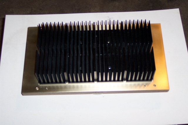
Heat sink side of the modulator
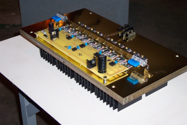
Shots of the finished modulator


4 FET RF Driver


The is going together daily so - - Stay Tuned for more!