
Issue 99
Scanned and prepared by Grant/NQ5T
A N N O U N C I N G
1992 AM FORUM AT DAYTON
The third annual AM Forum will be held at the Dayton Hamvention on Saturday,
April 25, 1992 at 1:15 PM Eastern Time in Meeting Room # 7
Issue 99
Scanned and prepared by Grant/NQ5T
A N N O U N C I N G
1992 AM FORUM AT DAYTON
The third annual AM Forum will be held at the Dayton Hamvention on Saturday,
April 25, 1992 at 1:15 PM Eastern Time in Meeting Room # 7
This year there will be a two-part program. Dale Gagnon, KWI1 will present "A Great California AM Station" - a pictoral review of W6HDU. Then Don Chester, K4KYV, editor/publisher of The AM Press/Exchange will lead a "Country-Wide AM Panel Discussion" to exchange ideas about good things going on with AM.
For two years in a row, we have packed the meeting room. Let's make this year's event bigger and better than ever. We'll have fun meeting other AM'ers, and we'll demonstrate that AM is returning to the mainstream in amateur radio.
DON JOHN, A MAN OF HONOR
Norfork, Virginia
A TRIBUTE TO W4YDF
With great sorrow, I would like to inform the AM community of the death of our beloved friend - Don John - W4YDF - better know as D J to thousands of ham operators across the country.
On February 29, 1992, DJ was found dead in his kitchen by his daughter, Donna John. It seems that he had a heart attack. He had open heart surgery in 1980 and had many health problems since that time.
DJ was very active in the AM community with myself, AA4TW, promoting the tradition of AM. DJ was a lifetime member of MARS and has given over 30 years of service to the MARS program. DJ was first licensed in AM radio in 1952. His first transmitter was a 813 rig built in a kitchen cabinet. I remember last March when DJ and I worked on his TMC rig all night long and how we laughed and joked. His workmanship was superior.
The world measures success in life with a material rule-how big, how much, how many. But that was never the guide that DJ used. The size of his heart was always much more important that how much he could get from you. DJ loved God, his family and his friends. The size of his heart was always many times greater than the size of his bank account; what he could do for you was always much more important than how much he could get from you. And that DJ's measure of success was a true one is amply evidenced by the many, many fine people who feel the loss of his passing.
DJ has gone ahead to prepare the way for us, and the bright fire of his spirit has been released from the body that finally had enough. We are grieved, for ourselves, for we shall miss that bright spirit. But we who remain miss that bright spirit. But we who remain are like the man who lives only in daylight the beauty he sees is brief, and local, and passes with time. It is only when night comes, and the glare is stripped away, that the greater beauty is revealed, and the starry majesty of heaven shines in power, in glory and forever. And there the soul of DJ shines bright, to bring us comfort when the dark, in turn, comes for us.
I wish just for one more time I could hear his voice and tell him "I love you my dear friend. My life is so much richer for knowing you and I never will forget you.
With deepest sympathy,
AA4TW
Mike McCoy
NOW AND THEN
THE BREADBOARD TRANSMITTER
PART IV
Harry Wells, AA6PP
Prepared by R. De Miranda, WB6UBD
Some Hints And Wisdom
The RFI problem with my 75T final was due to parasitic resonances in the neutralizing circuits. It was not fixed by changing those, but rather by adding some small chokes right at the final grid terminals in series with the grid lead. The chokes were made by winding half watt metalized resistors full length with #26 green silk wire.
Parasitic resonances are shock excited into ringing by this onset of grid current or plate current. The grid choke with the element capacity of the tube makes a series resonant circuit with a frequency not much higher than the highest band to be used with the rig. This limits the speed of the start of current or in other words it rounds off the corner when grid current conduction begins. It should be done to the final of every breadboard and in fact every rig that is homebrewed with triode tubes just to be sure, since it costs nil in cash or performance. It really works. The resistor is just used as a coil form with 15 or 20 turns of wire. Do as I say and avoid this problem of rocks bouncing off your shack.
If nothing else is available, satisfactory wire for the RF circuits can be obtained by stripping solid #14 house wire and stretching it till it begins to yield. Don't try to make long pieces unless you have help. Depending on your reach about three feet is as long as one can handle if using a vice and pliers. If you can tie the wire to something overhead it is easy to make one long piece and cut it to lengths convenient at the workbench.
You are going to need at least a 100 watt soldering iron to deal with the RF wiring and the ground plane. If the ground plane is very thick it might take a propane fired soldering iron to solder the grounds. Do not even think about screwed down solder lugs on the ground plane. Corrosion is a real possibility.
Submounting the tube sockets below the board is easy, looks good and may be an answer to too long plate leads or a tall tube. On a chassis type breadboard I wouldn't do it any other way, at least for the final tubes and bias rectifier.
I encourage you to cook up your own arrangement of tubes, but if triodes
are involved be safe and provide one watt of grid drive for every ten watts of
DC input to the plate. High or low Mu does not make much difference in
drive power requirements though it does make a lot in bias requirements.
Power grid tubes of vintage design just do require so much drive to get them
to draw required plate current. For triode finals in an AM phone rig you
have to provide enough drive to support more than double output under full
modulation. With tetrode and pentode tubes drive requirements are so low
that it is hardly considered.
Parts
This subject is so large it can't be covered very well and not at all completely. After tubes and sockets, the most prominent parts on the rig are the tuning capacitors arid coils. We wont go into coils at all, but variable capacitors have been manufactured in mind-boggling variety. Vintage Cardwells are great, but my vote goes for some of the types made by Johnson as the best looking. Offerings made by National, Hammarlund and even some of the variables used in battery broadcast receivers can be used with regard for capacity and voltage ratings. Large single section units can sometimes be converted to split stator if necessary. Molded mica transmitting capacitors seem to still be widely available in junk collections. These high quality items are necessary for RF coupling and high voltage bypassing, but filament and bias bypass service can live with the old Dubiler Micadon capacitors from battery sets and if you can find some usable ones, they have a place in a breadboard rig. They add a bit of charm in my opinion.
Vintage resistors are a problem either in carbon or wire. Vintage radio swapmeets are probably the only possible source for them. I like the IRC metalized resistors with their black, blue and white labels, but they were expensive when available and are scarce now. They have molded lead ends and the one watt size fit perfectly into grid leak clips.
In the tube chapter mention was made of breadboard sockets and the manufacturers of there listed. They were mostly made from black bakelite, but G-R and ICA did offer them in ceramic. These sockets were specifically made for mounting on wood and they were primarily intended for receivers and audio use. The ceramic types are really rare. My first rig used these bakelite breadboard sockets and completion was delayed about 6 months until I located some for 5 pin tubes. That was about 20 years ago. I have a stock now, but I don't consider them for RF service any more even though they work fine with receiving tubes and would be perfectly ok in the exciter of a breadboard rig. If clean arid undamaged they add an aura to a rig that uses them. Great for audio. Made in 4, 5,6 and large and small 7 pin types. Yes, there are two different sizes of pin bases on receiving tubes. Later they were made in octal as well.
Most easily obtained now are the ceramic sockets form WWII surplus. Hammarlund made some ceramic sockets that seem to have been designed for display on breadboard rigs. They were made from a gleaming white ceramic with a clear glaze. They are also a unique shape. You might prefer to have all wiring and small parts concealed and this is easy on a wood chassis since you can submount the sockets. Personally, I may submount some, have one car more on a metal bracket, or any combination that looks good and makes technical sense
Suitable knobs and dials are another real problem today and the breadboard does not look right at all without vantage dials. National type A, type B, type BM and type N were the kings of breadboard receivers and rigs. Type A and B come from the battery set era and you will see a them constantly in old magazines and handbooks. Atwater-Kent breadboard receiver knobs were very popular and available in the 1930s. Pilot made some very fancy vernier dials similar to National type BM which were of good quality and still are sometimes available at vintage radio swapmeets as are the 3 inch and 4 inch TRF broadcast set dials from the 3 dialers. General Radio made some quite nice metal vernier dials in 3 arid 4 inch size which never turned up in ham gear for some reason, but are perfectly suitable and l think rather desirable.
Transformers are a weighty subject and they are essential for ham gear. Usable transformers may be found anywhere, but metal scrapyards should be kept in mind. Power transformers from old vacuum tube TV sets are usable. I wind a lot of transformers, but not all of the ones I use. Snobery is not the reason for this, but rather weight and space. Typically, the breadboard rig of the middle 1930s used a separate power supply for every stage and a filament transformer as well. A 100 watt rig becomes 250 pound behemoth. I don't have the space and my taste runs to small neat things. In my rigs I put all of the filaments and sometimes the bias on a single core including the high voltage, low voltage and bias rectifier filament winding. So far it has worked great. I've done the same with dual voltage plate transformers with equal satisfaction and then put the filter chokes in the negative center tap and filter both supplies with one set of chokes. Separate filter capacitors are necessary for the two voltages.
These ideas are very effective for reducing size and weight, but most fellows will understandably use what they can scrounge. Still filament transformers for 5, 7.5 and 10 volts with sufficient current capability are rare and it might be necessary to put a new secondary on a dry rectifier transformer or something similar.
The insulation on the wires of many old transformers is completely rotten these days. The fix is easy. Just cut the old wire off about a half inch from the coil, scrape the insulation off the remaining stump, solder a new wire of suitable characteristics and color to the stump and insulate the solder joint with one or two layers of shrink tubing. If the shell looks bad you can wire buff the shell and the core and put new paint on it.
In the Los Angeles area and probably other cities you may quite possibly run into vintage transformers made in those good old days with amateur service in mind. Naturally you will want to use them if possible, but how do you find out exactly what they can do and their terminal arrangements. I may be able to help you. I have a large collection of transformer catalogs. Thordarson, Inca, Peerless and UTC go back into the early 1930s. I have fairly extensive data on modulation transformers made by these people with terminal and impedance data that I believe is complete for all Thordarson and possibly all UTC transformers. Also a bit on Inca. I need the make, part number, what it is if you know (Power, modulation, choke etc.) and a SASE. Address to: Harry Wells AA6PP [address omitted .. ed.].
Satisfactory filter chokes still seem easy to come by. For bias supplies I like the little choke assemblies that were used in B eliminators with one choke stacked above the other and the assembly held together with little bras rails. I loved them when I was a kid and have not recovered from my first childhood yet. I still love them and put them where they can be seen in my rigs.
If you can find or make a suitable can do not hesitate to put some ugly part in a new container or some new parts in a beautiful old container. Antique transformer cans and old tinfoil paper filter capacitor cans are naturals for this, but look around for possibilities. The forementioned items are hard to find now.
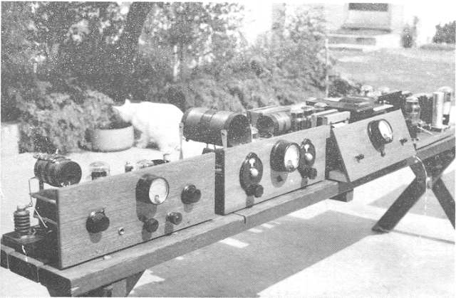
Photos are of the writer's 160 metre AM/CW transmitter.
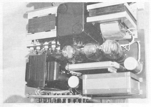
Fig. 1: The power supply. Homemade plate and filament transformers are shown on upper left and right side. The filter chokes are commercial. The tubes are two 5Z3's for the 700 volts to the final and modulator, and (to the left) an 83 mercury vapour rectifier for the 400 volts to exciter and speech equipment. Unit on bottom right is a 2 x 6 mfd 1 KV filter cap. The bleeder resistor is made from a stack of 6 vintage wirewound resistors mounted on a metal frame and encapsulated in a black compound.
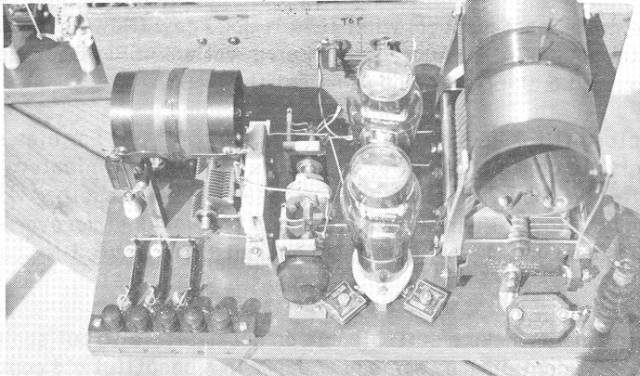
Fig. 2: The final amplifier. Pair of l0Y or 801's. For this band coils wound on bakelite forms are ok at reasonable power level. The visible knob drives the ganged neutralizing capacitors. Visible are the square Faradon .01 mfd capacitors used for filament bypassing. The final tank capacitor is a vintage Cardwell.
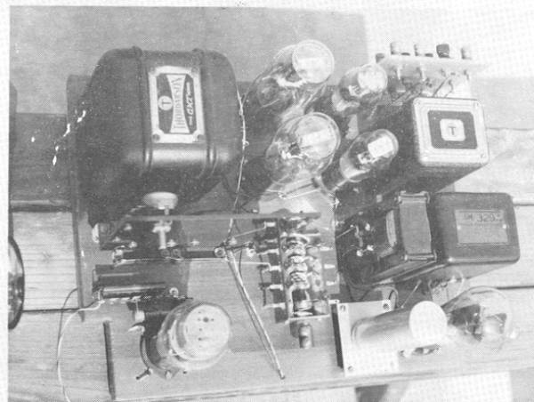
Fig. 3: The modulator deck. It was not quite finished when this photo was taken. Left to right at top is the modulation transformer, a pair of 801's for the modulator, a pair of type 56 cathode followers and an old time high fidelity input transformer. Just below the modulation xfmr is a small bakelite panel with the feedback ladders and a pot to adjust the feedback level. The tube in the lower left corner is a 2A3 used as the keyer tube for CW. The click filter is not yet installed. In the middle is a homebrew phone/CW switch made from parts from a pair of old knife switches. A special switch is necessary because of the number of circuits to switch, high filament current and high voltage from modulated B+.
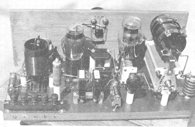
Fig. 4: The exciter. A 2A5 oscillator drives a type 45 buffer/driver. In the photo, a 2A3 is shown plugged in the socket. War surplus "grid leak" clips are holding the RF choke and a metalized resistor. The transmitting mica on two long ceramic insulators allows the shaft on the crystal switch to pass underneath. The capacitor couples between the oscillator and buffer.
Fig. 5: All four of the units laid out on a table. From left to right: exciter, final, power supply, and modulator.
To Be Continued Next Issue...
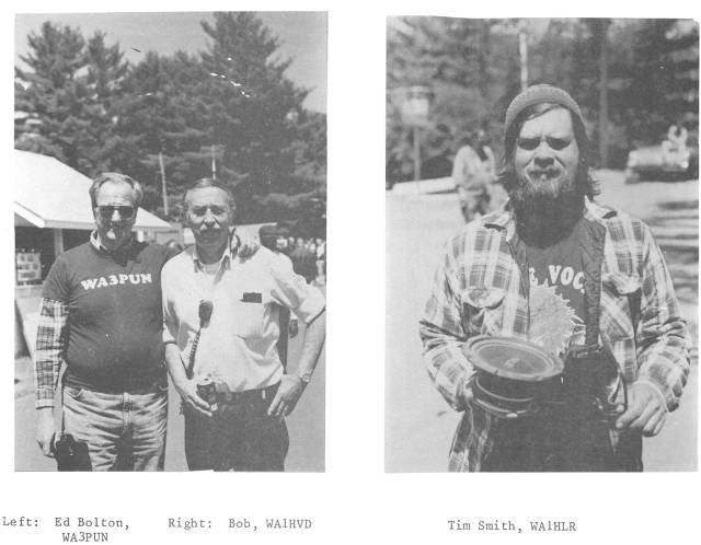
MEET THE Amers
Photos taken at Deerfield hamfest. TNX, WA3PUN
Are We Wasting Tube Life?
by Donald Chester, K4KYV
Davilyn Corporation in California recently sent out their 1992
catalogue. They list about every receiving and transmitting tube an
amateur or broadcast engineer would ever need, and then some. They even
list antique tubes such as the 01-A. The only catch is that their prices are
astronomical. The 01-A is listed at $50 each! For a good sample of tube
prices for vintage gear, I priced a complete set of tubes for my ham
transmitter, a rather typical plate modulated kilowatt using plug in coils and
triode finals. The following list only includes equipment in the
transmitter cabinet itself, excluding the VFO, microphone pre-amp, peak
limiter and main speech amplifier, all of which are in a separate rack.
| Tube Type |
Quantity Used |
Price Each |
Total Price |
| 8000 | 2 | $175 | $350 |
| 810 | 2 | 225 | 450 |
| 872-A | 4 | 50 | 200 |
| 866-A | 2 | 25 | 50 |
| 211 | 1 | 150 | 150 |
| 807 | 1 | 15 | 15 |
| 6AG7 | 1 | 8 | 8 |
| 2A3 | 4 | 75 | 300 |
| 523 | 1 | 25 | 25 |
| 83 | 1 | 25 | 25 |
| 80 | 2 | 10 | 20 |
| VR-150 | 2 | 15 | 30 |
| 6AS7 | 1 | 8 | 8 |
| 84/624 | 1 | 30 | 30 |
| TOTAL | $1661 |
Luckily, I have accumulated a comfortable reserve of spares for each tube, and additional tubes are never passed up at fleamarkets when the price is attractive. At the prices listed above, maybe we should store our spare tubes in a secure vault; they are literally worth their weight in gold. Of course, most of us can find tubes at more reasonable prices. Hamfest dealers often bring hundreds of receiving tubes and sell them for as little as $1.00 each. Sometimes larger transmitting types are available reasonably, as well. But how mach longer can we count on this supply to last? If tubes can really bring prices like those listed above, the dealers are unlikely to continue to haul them from hamfest to hamfest for $1.00 each. All owners of vintage tube equipment are advised to immediately begin stocking up as many spares as possible, and to take whatever measures we can to extend the life of the tubes we own.
Good information on tube conservation can be found in articles from amateur and commercial radio publications from the early 1940's, when worries about tube life became urgent because of war shortages. Today, we face even more critical a shortage, since fewer and fewer tubes are even being manufactured, and many of our spares have been lying idle on the shelf for decades, possibly collecting gas. Anything we can do to prolong tube life and still keep them operating at peak efficiency will be a boon to our own stations and vintage radio as a whole.
FILAMENT VOLTAGE: One of the critical factors in tube life, especially the thoriated tungsten variety, is proper filament voltage. Manufacturers recommend plus or minus 5% the rated voltage. It is just as hard on the filaments of transmitting tubes to run them at too little voltage as it is to run the filament voltage too high. Some manufacturers claim tube life will be extended if the filament voltage is reduced, as long as the tube continues to give the desired performance, including peak emission demands. I have always preferred to play it safe by maintaining the rated filament voltage as closely as possible. If you have good line voltage regulation, perhaps life could be extended by precisely maintaining the filament voltage at 5% below the rated value. Under no circumstances should filament voltage be reduced to the point that grid current or plate current drops off, that positive modulation peaks become clipped, or that downward modulation appears. Thoriated tungsten tubes will be quickly ruined if operated so that the filament is "starved" for emission.
BREAKING IN THE FILAMENT: If the tube is brand new, or has been idle on the shelf for an extended period of time, do not stick it in the transmitter and immediately apply full plate voltage. It is likely that a few gas molecules have accumulated in the tube, and the electron emission from the filament at full plate voltage will result in high velocity bombardment of these gas molecules, which ionizes the gas and scatters electrons, much in the manner that a cue ball scatters the rest of the balls on a billiard table. The result is that high velocity electrons will be projected in random directions and many of these will collide with the filament and "sandblast" away the thin layer of thorium on the filament surface. RCA recommends the following procedure. (1) With no other voltages on the tube, apply filament voltage at the normal value for 15 minutes. (2) Apply reduced rf drive (about 75% normal drive) for 15 minutes. (3) Apply approximately one-half normal plate and screen voltage for 15 minutes or until stable performance is obtained. (4) Increase rf drive to normal value. (5) Gradually increase plate and screen voltage to normal, making sure the tube is operating with stable performance each time you increase voltage. The theory of "break-in" is that as the tube's elements are gradually brought up to full operating temperature, the hot anode and grid will absorb most of the free gas by "getter" action, while the plate voltage is reduced to minimize the "sandblasting" effect. Once the residual gas is cleared out, full voltage is applied for normal operation. In the case of modulator tubes, a modified break in procedure can be used, in which the filament is operated for at least 15 minutes with no plate voltage, and then with plate voltage reduced to a very low value, cut the bias until plate current is noted. Gradually increase the plate voltage, keeping the bias at a value that plate dissipation remains at a safe level. Gradually the tube is brought up to full plate voltage and normal grid bias. Of course, this break-in procedure requires some sort of variable plate voltage and bias control.
MURCURY VAPOUR RECTIFIERS should be operated at the rated filament voltage, and maybe about one percent above; never below. Sufficient time must be allowed for the filament to reach operating temperature and mercury vapour pressure to become normal before high voltage is applied. When tubes are first installed, or they have been tilted so that mercury collects on the glass envelope or the plate structure, the tube must be run with the filament on and no high voltage applied, until the mercury has all evaporated from these parts. Otherwise, flashover will occur, which may permanently damage the tube. Manufacturers recommend at least 30 minutes, but several hours will not hurt, just to be on the safe side.
INRUSH CURRENT: Provisions should be made to limit the initial filament current when the tubes are started up. This can be done by inserting a resistance in the primary of the filament transformer when voltage is first applied, or by bringing up the voltage slowly with a variac. Another possibility is to use a transformer with a higher than normal voltage, and drop it back to normal with a resistor in the primary (be careful to maintain normal filament voltage within the safe range, as described above). When closing down the transmitter, it is a good idea to lower the filament voltage gradually, after the high voltage has been removed, to reduce the thermal shock caused by sudden cooling.
STANDBY OPERATION: A neglected factor may be needlessly robbing us of the maximum usable life of both transmitting and receiving tubes. In a typical amateur station, the tubes in the transmitter and receiver often operate for substantial periods of time with full filament voltage, but with plate (and screen) voltages removed. We have all heard that it is harmful to frequently turn the filaments on and off. It is commonly believed that it is better to the let the filaments burn all day than to turn them on and off several times per day. This is probably true, especially if precautions are not taken with transmitting tubes to limit inrush current and thermal stuck frond sudden cooling. However, it is apparently harmful as well to run certain tubes for long periods with filaments lighted and no plate voltage applied. The R-390A repair manual (TM 11-865A) states (page 24, section 27): "When the receiver is not to be used for a short interval but is to be maintained in a state of readiness, turn the FUNCTION switch to STAND BY. Caution: The FUNCTION switch should not be left in the STAND BY position for too long a period of time. Under this condition of operation, with the filaments lighted and no plate voltage applied, the useful life of certain vacuum tubes may be shortened."
Thus we are left with a dilemma: turning the filaments on and off shortens tube life, but so does leaving them on without plate voltage. This poses no problem with broadcast transmitters since they operate continuously throughout the scheduled broadcast day, and are normally shut completely off when the station is not on the air. But with amateur radio, the transmitter and receiver are both called on to operate for a substantial amount of time with the filaments on while in stand by, since the transmitter must be maintained in a state of readiness while receiving, and vice versa. Hams may therefore experience an abnormally high rate of tube failure when a commercial broadcast transmitter is placed into service in an amateur station, even though all the recommended precautions are taken with the precious tubes.
This dilemma is addressed in the Application Guide for RCA Power Tubes, under "Standby Operation". During standby periods, the tube may be operated at decreased filament or heater voltage to conserve life. It is recommended that the filament or heater voltage be reduced to no less than 80 per cent of normal during standby periods of up to 2 hours. For longer periods, the filament or heater should be turned off." To protect receiving type tubes, the circuits of receivers, speech amplifiers and other equipment used with the ham station can be designed or modified so that the plate voltage is not completely removed when the equipment is operated in stand by.
One explanation of the reduction of tube life by operating the filament without plate voltage is that under this condition the hot cathode emits electrons, but there is no positive plate or grid potential to attract electrons away from the filament. Therefore, the electrons remain near the filament and form an "electron cloud" around it. These electrons are set into mechanical vibration by the magnetic field resulting from the a.c. filament current, plus any stray magnetic fields from nearby transformers or current carrying wires. These agitated electrons bombard the filament of the tube and produce a "sandblasting" effect much in the same manner as in the case of electrons colliding with gas molecules as described earlier in this article. This would suggest that full plate voltage is not required during stand by operation, but that a reduced plate potential sufficient to maintain a small stand by plate current would be sufficient to attract the electrons safely away from the filament surface.
By maintaining certain precautions with our tubes, it is hoped that we can avoid needlessly shortening tube life in both transmitters and receivers. The suggestions in this article are by no means intended to be the last word in tube conservation. In fact, it could better be described as the "first word", to promote investigation into what really works to make tubes last longer, while we still have a supply of tubes left to use in our vintage equipment. Clearly, more concrete data is needed. If you have any knowledge on this subject from your own experience, from published articles in your electronics library, or from any other source of expertise on this subject, please share this information with your fellow "hollow state" enthusiasts. The AM Press/Exchange invites you to send in articles or data for publication that will further shed light on this subject before it is too late!
EXCHANGE
FOR SALE: Drake 2B with manual $1400, best audio quality, engineer/musician aligned, gladly deliver Dayton Hamvention.
WANTED: 6G6-G tubes (3).
FOR SALE: BC 221 frequency meter in metal portable case with built in power supply $45. Clegg 6 metre transceiver with power supply, $150. Type 813 tetrodes $15 each. T.S. 413 C U signal generator covers all amateur frequencies $100. 7 and 9 pin miniature tubes .99 each. Octal and loctal based tubes $1.99 ea. Wanted NCX 3 power supply, Unique wire tuner.
WANTED: Old style pushbutton a.c. light switches and cover plates
Wanted: Hallicrafters SX 88 in good to excellent condition.
WANTED : ARTICLES AND P H 0 T 0 S . Our manuscript tray is empty again. We request that articles be submitted camera-ready, but if that is impossible, manuscripts in any form will be considered, but publication will be delayed. The AM Press/Exchange
P.S. We are particularly interested in reader input on the subject of
tube conservation. See article in this issue. Ed.