
Issue #107
Scanned and OCR'ed by Mike Warren, W5MAZ
![]()
1300 Emission Types: Fraudulent FCC Tactic Exposed
We recently reviewed material in our files on the AM power issue. Carefully studying letters and documents, we discovered how the Private Radio Bureau arrived at the figure of "1300 emission types" allowed under the amateur rules. Our documentation demonstrates the manner in which the PRB used this number to deliberately mislead members of Congress and President Bush’s staff, regarding the Commission’s refusal to follow through on its commitment to reconsider the AM power issue when the grandfather clause expired in 1990.
Many individuals wrote letters to the President and members of Congress to complain about the FCC’s obstinate determination to reduce the maximum legal power level for AM transmission, despite the overwhelming volume of comments from the amateur community supporting retention of the long-standing AM power limit. These complaints were forwarded to the FCC, and the Commission responded with a form letter which we quote in part:
Dear (Senator …/Representative …/Mr. President):
Thank you for your recent letter on behalf of Mr./Ms. (insert name of Constituent). (Constituent) requests that the Commission reconsider its decision concerning the transmitter power standard for amateur stations transmitting emission type A3E.
The decision that (Constituent) refers to denied three petitions for rule making seeking to amend Section 97.313 (b) of the Commission’s Rules... to promote emission type A3E by allowing amateur stations transmitting this particular emission type a maximum power output four times greater than the output power allowed stations transmitting any of the other 1300 emission types. The Commission denied these petitions, finding that the issue is one that the Commission had previously considered and denied..
Let us examine the above text. The issue "previously considered and denied" refers to the original rulemaking decision to reduce AM power. The FCC failed to mention to the Senators, Congressmen and President that the original power limit docket decision specifically expressed a commitment to reconsider the AM power reduction before it was to take effect in 1990.
The FCC goes on to mislead the reader with an erroneous claim that the "three petitions" sought to change the rules to give AM a substantial power advantage over other modes. In fact, two of the three petitioners did not seek to change the existing rules, but to keep in place the AM power level that had existed for over six decades, ever since voice transmission was introduced into the Amateur service. The figure of "four times" is based on one petition, submitted by SPAM, which sought to allow AM 1500 watts carrier power. The FCC does not explain to the reader that the newly adopted p.e.p. power standard gives an inflated figure for AM power, compared to other modes, due to the nature of the AM waveform.
Many AM’ers have remained mystified by the FCC’s claim that AM is just one of more than "1300 modes of emission" used in the amateur service. To further demonstrate how insidious the scheme of deception by the FCC’s Private Radio Bureau really was, let us examine the basis of this claim. One of our readers wrote a letter to Ralph Haller, Chief of the Private Radio Bureau, and we quote in part:
"I would like to call your attention to the errors that your staffer made in the above letter (referring to the form letter quoted earlier). First, Amateur Radio Operators are not allowed 1300 emission types. Please refer to Part 97. Second, (hams) have never been authorized 6.0 kw of power as referenced in your letter. The Amateur Service has always been authorized 1.0 kw of AM power and the Amateur community only wishes to retain this privilege."
Here is Haller’s response:
"Part 97 of the Commission’s Rules, 47 C.S.R. §§ 97.1-97.527, uses a simplified system for designating the various emission types that are authorized to be transmitted by an amateur station. This system, which is defined in Section 97.3(c) of the Commission’s Rules, 47 C.F.R. § 97 .3(c), consolidates the complex emission, modulation, and transmitting characteristics terminology of section 2.201 of the Commission’s Rules, 47 C.F.R. § 2.201, under nine terms that are more familiar to amateur operators.
The simplified system is based upon the working paper, Designation of Emissions in the Amateur Service, by Paul Rinaldo. This paper states that the number of emission designators used in the amateur service increased to 1296, as a result of the emission designator system adopted at the 1979 World Administrative Radio Conference. This emission
designator system is incorporated into Article 4 of the international Radio Regulations as well as Section 2.201 of the Commission’s Rules. Dr. Rinaldo’s paper was published in August, 1987, (by the ARRL). The number of specific emission types was rounded to 1300 in the discussion of the need for simplification when Part 97 was reorganized..."
We obtained a copy of the working paper from ARRL. The SUMMARY on page vii explains where the above figure comes from:
"Emission designators have grown in number and specificity to the point where their continued use in the amateur service has become a disadvantage. In (sic) the implementation of new emission designators adopted at the 1979 World Administrative Radio Conference brought the number of emission designators used in the amateur rules from 14 to a choice of 1296 if all combinations were used (emphasis ours). Only a few of the possible emission designators were written into the amateur rules effective January 1, 1985. Others have been added by subsequent rule changes, and many more would be needed to cover all emissions in actual use and others for likely and desirable experimentation in coming years."
Thus we see one more tactic used by the PRB to conceal in bureaucratic jargon the facts of this issue. For the purpose of misleading members of Congress and the President’s staff who inquired about constituents’ complaints, the PRB’s form letter failed to distinguish between actual emission types used by amateurs, and hypothetical emission designators created at the WARC conference by a complex new system of definitions. In other words, the vast majority of those "1300 emission types" exist only on paper as far as amateur radio is concerned. To the technically uninformed, the FCC’s argument is more convincing when AM is only one of 1300 modes used by amateurs, as opposed to one of fourteen.
EDITOR’S NOTE: Readers interested in the complete text from which the above quotes are taken please send your request along with SASE to AMPX.
![]()
Washington Lawyer to Head FCC
Reed B. Hundt, 45, a well respected Washington attorney who went to high school with Vice President Al Gore, is President Clinton’s choice to head the FCC, according to W5YI REPORT. Hundt does not have a communications background; be is widely known as an antitrust litigator. As television, telephone and computer concerns seek to merge expertise, antitrust concerns are a growing factor in the FCC’s work. Recent FCC appointees have tended to have legal, rather than technical expertise, leaving technical decisions, such as the AM power limit issue, up to "career civil servants" employed by the FCC’s various bureaus.
![]()
Open Forum
Editor, AM Press/Exchange
Urgent help did come my way as someone put the S.O.S. announcement in issue # 101 (page 7). I didn’t send in the request, but I think I know who most likely did. Two old timers and champions in their radio field came to my assistance.
One was Bob Becker, W7OD, a World War II Army Signal Corps code instructor who now lives in Normandy Park, WA. He sold me a Hallicrafters SX-130 at swapmeet price along with a wealth of information on code education and weather stations worldwide to practise on. Next was Mr. Art Robertson, W0IWV, La Junta, CO, who gave me a Hallicrafters S-20R that came in handy when the SX—130 started to hum badly. An amazing ace of a ham, Mr. Robertson is ex-W9DPZ, W9DPZ/KB6 and W5LSP. He operates airborne, mobile and fixed base, is a QCWA life member and an Old Timers life member, holds W.A.S. phone and CW and 10 metres W.A.S. phone and CW. That is going to be hard to beat. Art sent me his last picture QSL card showing him by his airplane.
The VEC’s did come to my house. I passed the Novice, Tech, and General tests in February, 1993 and am KD6TEF now. All my receivers and old transmitters went west and I am still building my station but don’t dare to buy anything too expensive as I suspect the house is haunted to send my stuff west, HI.
Many thanks to all who helped me to be a happy ham again.
Sincerely,
John Makara
EDITOR’S NOTE: At age 81, John finds it difficult to get out of his house. His first ham licence expired during WWII while he was in the 11th Army Airforce, L31 Outpost. If someone is able to give him a hand getting his equipment on the air, you may contact John at 9263 Rose St., Rosemead. CA 91770-1458.
![]()
Manuals For Vintage Equipment
Need manuals for vintage equipment? Contact W7FG at 3300 Wayside Drive, Bartlesville, OK 74006, or tel. (918) 333-7893 for price list. Manuals are mailed within 24 hours of your order. Gary says he is always looking for additional manuals, and he will reimburse you for letting him copy yours.
![]()
Dublier Micadon Capacitors
Harry Wells AA6PP
Of all the mica capacitors that made the market by 1930 the Dubi1ier Micadon was by far the most ubiquitous. It came on the market in answer to the need for a fine quality item to be used in broadcast sets. Over the market life of the product it was offered in a variety of models and in capacity ranges of from about 100 PF to 10,000 PF. I have just ran a number of these through my HYPOT tester to determine what kind of voltage they could be expected to withstand. I tested a dozen of them. One of these was shorted before testing. Several more were defective, but this was not known until the test was finished. Part by part here is what I found:
.002, 1.5KV. .00025, 6KV. .006, 750V. .002, 9KV.
.005, 5KV. .006, Shorted. .01 approx 7KV. .0025, 5KV.
.01, 3.5KV. .00025, 5KV. .0005, 5KV. .00025, 5KV.
Part #4, the .002 PF sparked over the outside at approximately 9KV. It did not fail. Up through part #7, the .01PF, I increased the voltage to the point of corona or spark if I got no corona warning. The smaller values do not store enough energy to destroy themselves even if they spark through. In the case of the .01 it did store enough energy to destroy itself and shorted at about 7KV and remained shorted. It was not my intention to destroy these parts so the remainder of the tests were limited to 5Kv maximum. The second .01 indicated failure approaching at the 3.5KV voltage and so I stopped at that point on that part. It did not fail.
We can say that one third of these parts are unusable for any purpose except filament bypass in small rigs. The rest should be perfectly OK for use to 400 volts DC in exciters. I only use them for filament bypass myself and this new knowledge will not change that.
The .01 that failed was a rather scarce type 640. I dismantled this one to see how it was made. All of the metal parts outside were of nickel plated copper. Inside one linen filled phenolic cover was a heavy phosphor bronze spring to keep pressure on the plates for electrical stability. All Micadon’s were boiled in paraffin to seal against moisture. The plates were tinfoil.
I removed one single mica dielectric plate and put it on the Hypot tester. It was 1 and one eighth inch square. My micrometer indicated .002 (two thousandths) of an inch thick. The mica was put on a flat metal plate and a small round electrode set right in the center. It finally sparked over the surface to the metal plate at about 15KV. It never did puncture in about 15 seconds of testing at 15KV. Spark path more than a half inch long.
There were some ersatz items not made by Dubilier on the market in the later 1920’s. Electrically they may have been just as good, but they had the appearance of cheap imitation. Micadon’s are still not very hard to find at antique radio swapmeets.
The mica capacitor molded into a block of bakelite turned up in stores and in sets around 1930 as the sale of AC radio receivers got seriously under way. Occasionally Micadon’s or the imitations turned up in AC sets when penny pinching manufacturers found usable values at giveaway prices forgotten in the warehouses.
![]()
A Simple Overmodulation Indicator
Harry Wells AA6PP
Around the AM hamshack one of the really needed items is a reliable and simple overmodulation indicator. One that takes up no space is certainly desirable and if it is always available that makes it just about perfect. Some time ago I came up with a design for one, though I can’t believe it is something new under the sun.
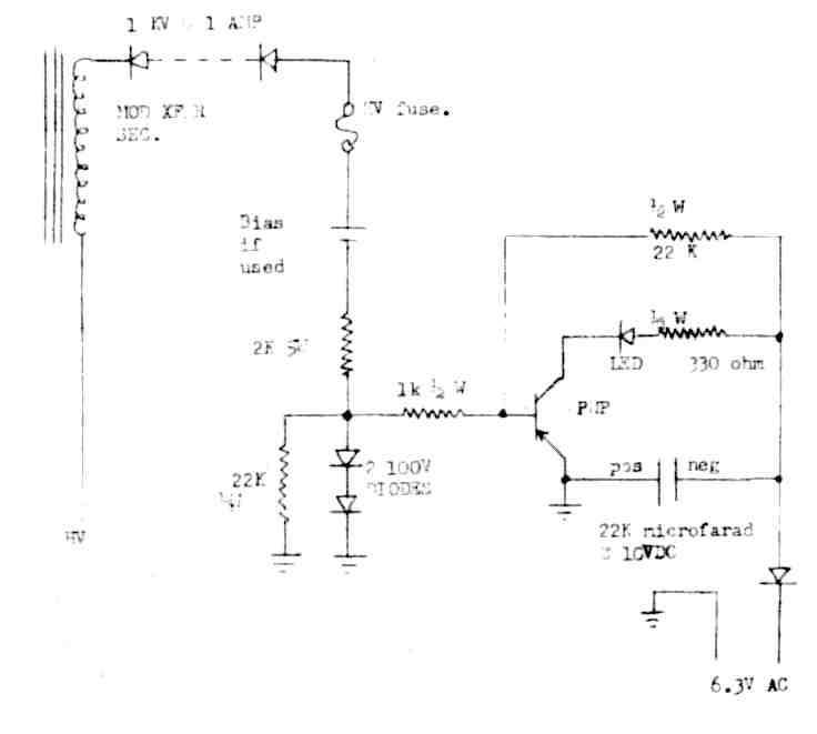
It is just a transistor switch that turns on and lights a LED when the voltage on the secondary of the modulation transformer swings negative in relation to the ground or B minus rail for the final amplifier. It is intended to be built into the rig it will be used with and because of the high voltage it is not safe or practical to apply it any other way.
The forward voltage drop of the high voltage isolation diodes must be overcome before the unit can turn on the flasher so it does not indicate exactly 100 per cent modulation in the negative direction, but if you desire better accuracy some improvement can be accomplished by adjustment of the number of diodes and inclusion of a bias cell or battery if you are into real high voltages. The cell is put into the diode string, preferably at the low voltage (flasher) end negative side down. Silicon diodes begin to conduct somewhere between 0.4 and 0.5 volts, though conduction at full current happens somewhat higher. If you use a switch transistor with HFE around 100 it is realistic to figure diode drop at 0.5 volts per diode in the foreward direction. A single alkaline cell is 1.2 volts so in a rig with 500 to 600 volts plate supply 2 1000 volt diodes would be needed and one cell would shift the overmodulation point from about 1 volt below the ground rail to 0.2 or perhaps 0.3 volts above the ground rail. So indication would begin just before clipping in this case. None of this is at all necessary to performance more than adequate for ham purposes.
The minimum number of diodes used of the 1 KV at 1 AMP variety is determined by the rig plate voltage times 2½ which includes safety voltage protection for a rig that is modulated to 100 per cent in the positive direction. If high level asymmetrical modulation is used to exceed 100 per cent more diodes will be needed to stand off the peak voltage from the modulation transformer.
Power supply for the flasher can consist of a half wave rectifier on a grounded 6 volt filament supply, a separate small supply with a filament transformer or even a tap on a bias supply bleeder. Since significant current is flowing only when the flasher is lighted average current is minimal even with fairly heavy overmodulation. A large filter capacitor can take care of the peak current requirement which is not over 20 mills. Average current is much lower.
Several years ago I built the experimental model on a solder lug strip and left it sitting on the bench outside of the rig. With the genius I sometimes bring to my projects I put the ground and the high voltage next to each other on the lugs. - Whatever can go wrong will, and after about 2 weeks it went up in a spectacular ball of fire and smoke. Be safe. If you build it treat the high voltage area with respect due to anything that has double the final plate voltage on it.
Except for the possibility of adding bias and adjusting diode voltage drops no possibility and no need for calibration exists. It can be built very small and scattered around in available space in the rig. It really breaks down into 3 subassemblies, the diode string, the switching unit and the power supply. I recommend a low current fuse in the diode string just in case of diode failure.
Obviously there is nothing critical in layout or wire placement after the diode string and the flasher can be located outside of the rig in an operating console. Up to 20 feet of wire to the LED should be no problem. It might tolerate much more.
Various transistors may require adjustment of the transistor base bias resistor because the switch should be close to on at all times. If it remains lit either increase the resistor to the collector supply or reduce the base resistor which goes to ground.
Higher collector voltages require adjustment of the base bias, the LED current limit resistor and the voltage of the filter capacitor. Maximum LED current is about 20 mills for most commercial lamp diodes and good ones make plenty of light with 12 to 15 mills.
Overmodulation indicator schematic
![]()
YOU COULD BE USING A SIGNIFICANT READABILITY IMPROVEMENT ON YOUR AM RIG BY SIMPLE PREEMPHASIS AND DEEMPHASIS
By George A.H. Bonadio, W2WLR, 373 East Avenue, Watertown NY 13601-3829
Part VI
WHAT HAS BEEN DONE WRONG
Many of our sets were "corrected," from the original design, by the use of "much bigger" blocking C's in the audio path. As we can see now, by the B formulas, these much larger C's extended the bass frequencies to undesirably low frequencies. Sometimes they had to be reduced in values because motorboating low frequencies occurred. Sometimes these were surpressed by larger C's in the decoupling filters of the first stages.
Meanwhile, nothing was done to bring up the treble from its surpressed status. in non-competitive local contacts they had "nice deep bass" and a treble that was hearable only because the background noises were so far below the very high "local" strengths. However, out in the real world of competition with all types of noises, these AM signals were pointed to as proving that AM is very inferior to SSB, in the real world." We saw this so often that even we AM devotees were starting to believe it.
Now we know that AM call have an unused high quality "loudness" of as much as +10 dB, to the ear, without apparent distortion. As shown in Figure 3, earlier, AM can now use three advantages. We use much more "time occupation" displacing the reception of lower strength noises at those time slots.
We use preemphasis to build up our weaker, but essential to readability, treble, to the maximum headroom available. We compress, at a faster than standard compression rate, so the weaker portions do get extra gain, before the ear can detect an unnaturalness.
Frequently I mention that I am writing a series on improving AM, but I avoid actually asking for a report. On 15M I just contacted Howard, W2NRM, of AM PRESS EXCHANGE history, who ventured, "You are louder than the Broadcast Station. You sound just great." On 75 M, last night, Victor, WD8DWR, said, "Fine copy. You sound like a million dollars. Audio is doing a nice job, real beefy. I do like the sound of it. It's clean, definitely clean. No hash that's unwanted, stays up real good, real beaudatious." And late last night, on 75 M, I demonstrated about + 20 dB (= 100 x voice energy) of compression, into our round table, and someone reported, "not bad, not distorted, folds back on you, but it gets through."
IF YOU DID NOT WAIT
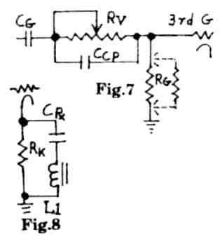
Some more enthusiastic operators have already flattened out their audio, with no preemphasis to correct it. There are compromises that will help you wait a little: longer for the revised preamplifier circuit. A temporary preemphasis controller may be inserted, as in Figure 7.
It is only a CCP and RV inserted before the third grid. RG should not be above 390,000 Q. Your ohmmeter will give you a satisfactory reading, about 320,000 W if you have 1,000,000 W in parallel with an original 470,000 W RG Your RV should be temporally soldered in place away from chassis capacitance, maybe as a Radio Shack circuit board rheostat, hanging in space.
It is compromised to allow some savings in gain, which gain is your limiting factor. However, yourr audio will be wider on the band, so the curve has been compromised to keep that extra width modest, temporarily. Do not give me credit for how wide you will be, nor should you presume that you will sound as loud as with the preamp, filters and all, later. Its response curve will show at a little left of the top of the D curve, and rounding at the top right end. Do NOT say that I advised it. It is your doing, by being too hasty.
A different temporary approach is to use the circuits of Figure 8, twice. It provides some rounding off of the excess treble. However, the curve resulting is difficult to match to resemble earlier curve D. It is useful only in place of the first TWO cathode bypass C's. It uses surplus 88/22 mH toroids tuned in series with a resonating C for near 3,150 Hz, where it effectively bypasses RK.
Their combined fall off, beyond the peak, is only about 10 to 12 dB, which is better than Figure 7, but hardly effective in bandwidth narrowing. Try using .068 uF (68n) and 44 mH (2 X 22), and reducing the RK to get a better curve shape.
In Figure 7 the rheostat RV is 3 to 10 times the value of RG. Then CG is the proper blocking CG for RG at RG X CG = 5,000 B ± 20%. Meanwhile CCP is the Compromise preemphasis in RG x CCP = 47 B ± 10 %. I expect you to run out of gain to modulate with in your normal modulation posture before you can increase the RV to the optimum effects.
Instead, with the rig gain all the way up, and no excess modulation, the bottom flat part of your D curve will probably be above that D shown. If' RG is combined 470,000W and 1,000,000W , they are equal to 320,000W , so CG by RG x CG = 5,000, is .015 uF (15n) (at 400 V or more).
Both of these circuits must be considered as temporary, at less than ideal, because our ideal is attainable.
DIAGRAMS AND COPIES
Do make extra machine enlarged copies of your original diagrams. Use one set for marking, in one color, the changes that have been made before today. Use another copy and color for calculating B values of present values of C & R (or Z) = B, with any corrections to be done, either inserts or elimination's. Use another copy for showing, in another color, what you have completed.
You should show your signal output voltage divider in its permanent insertion. It should be able to be brought out, though some terminal, to be useful as a scope source, or audio, or meters. This audio may also be used to produce a true trapezoid pattern. It will probably be about 20 volts of audio, with no DC.
TRAPEZOIDAL ERRORS
My Heathirit SB 610 scope produces a false "trapezoid" pattern only from RF! It rectifies audio, from the coax RF, and applies that, with that RF, itself to produce a pattern. What is wrong, with that procedure, is that it does not include the distortion that happens in the final RF stage.
This means that very non-linear modulation still shows up, on the SB 610, as very linear modulation. I inserted my audio, and switched to RTTY, and got a true representation. Rolling my RF drive down, to produce poor linearity, now, does show, where it does not show on their RF TRAP position, in the SB 610.
The trapezoidal pattern is very useful in setting the gain positions on both the output drive from our new (to be) preamplifier, premphasizer, compressor, filter and the related rig's gain control. Ideal, probably, is to end up with the optimum level for the trapezoid almost reaching a closed triangle with the gain control straight up. The output level control on the above outboard box will allow this, and we will know that we are not overdriving an early audio stage, nor picking up low level hum and noises.
NO MORE OVERMODULATION
In 57 licensed years, I have done more than my share of overmodulation. As W8OMM I was sometimes phoneticized as Old Mushy Modulation. The rule has been to get a few peaks up to overmodulate so that the average would came up by, maybe, a whole 2 dB. Always I was worrying about, was I too heavy or too light. Now, with this gear, it is a pleasure. My average is up even better, and I don't ever overmodulate.
If I get words up 50 % or more, the lower energy is already being brought up by even more dB, depending how long they happen after a stronger sound. After I reach the top level, which I set, the further top peaks stay at that level, even for the next 20 dB of shouting.
Only the lower levels come up further, filling in vacant time and unfilled energy areas, so that I am just louder without apparent overmodulation distortion. The streaky trapezoidal pattern just gets brighter as more readability is packed into the unused time/frequency spectrum.
Delightfully I enjoy zeroing upon a CQ'er, answering him with only one simple "W2WLR" and hearing them come back with my call letters correct. I think of it as "Phoneticless Phone". I enjoy QSO's of hours with no phonetics needed. I don't even remember the phonetic code any more.
WE HAVE LIMITATIONS
In order to squeeze in the most quality audio, we need to start from a level which we can all easily reach. We will automatically have the greatest undistorted powers, per stage, with this response.
It also gives us the compatibility with any PRE-box which anyone wants to use ahead of it. If you have a number of AM rigs, do one (preferably not a DX 100 because of its bass limitations) first. Later, I expect that you will want to flatten all of the other's audio. Then you can feed any one with your one PRE-box.
Wet can not pack in more than 100 % modulation on any audio frequency. This is our limitation. If there is any more to be improved in this system, it will have to be in making at least one receiver IF selectivity position to fit our D curve.
Looking at curve D we can imagine that it has an equal mirror curve to the left of its shape to the right of 0 Hz. This would be like the receiver IF curve that would fit our D exactly. In practice, thankfully, it does not need to be as perfect a fit as we need to get our last dB into modulation and transmission.
To Be Continued...
![]()
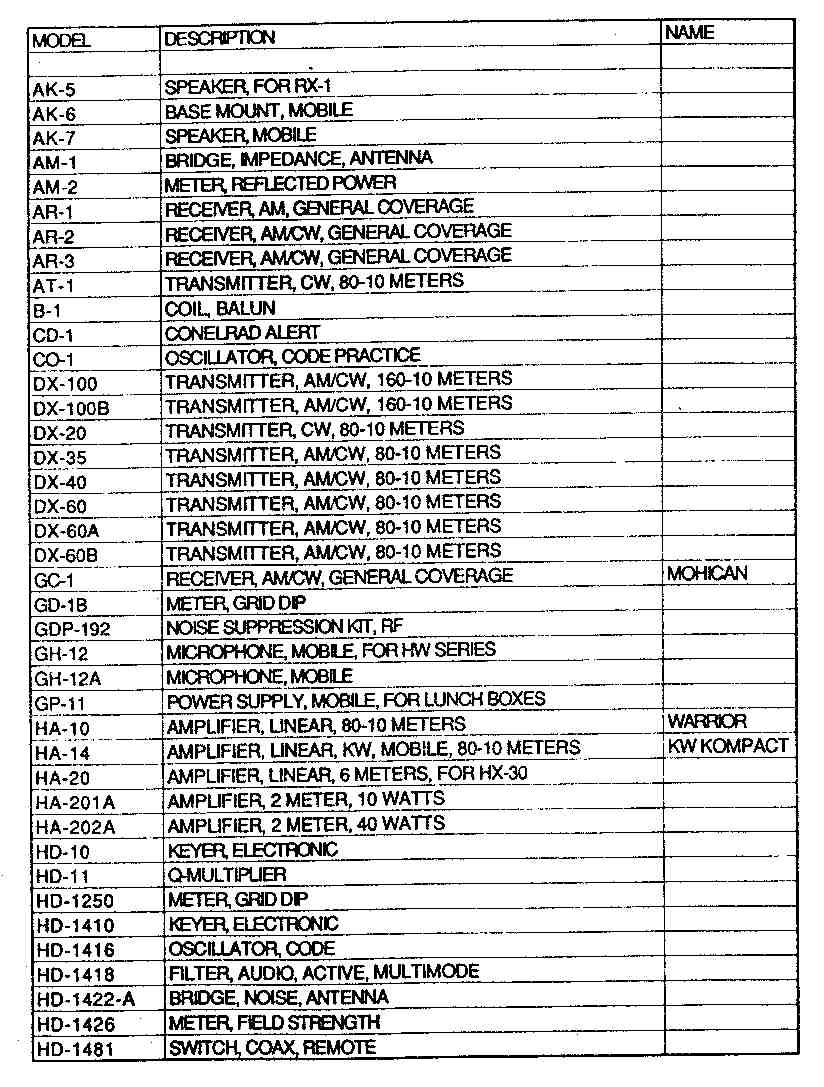
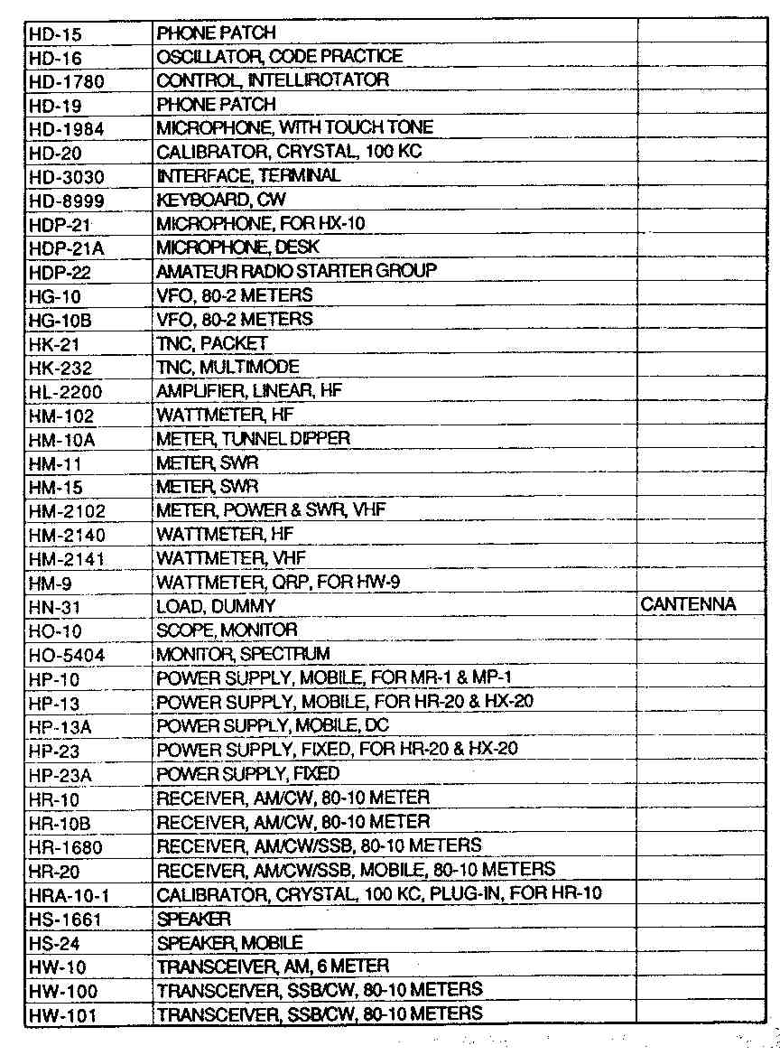
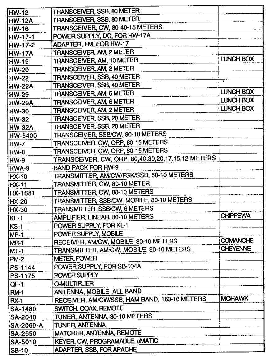
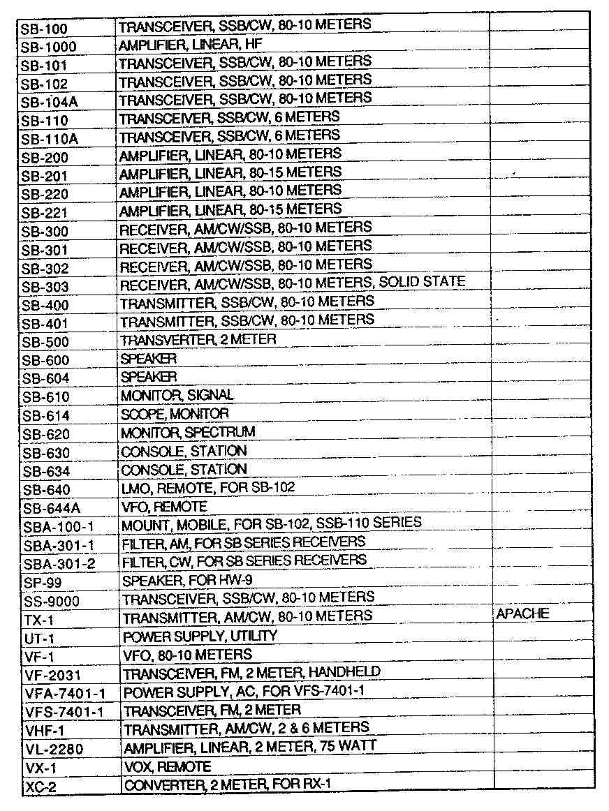
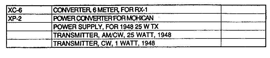
A Complete List of Heathkit Equipment
This list was compiled by Marty Drift, WB2FOU. He says it is a complete list of everything Heathkit ever made, except for maybe one or two pieces missing. Readers are invited to send in any additions to make the list complete, if you discover anything missing.
Heath Page 1
Heath Page 2
Heath Page 3
Heath Page 4
Heath Page 5
![]()
EXCHANGE
(Names removed since this is a past issue)WANTED: Johnson VFO (Viking I or II), RCA 7094 tube, Nillen 90711 VFO, Gonset G-76.
WANTED: Feet for the National NC-200 receiver and matching speaker. Power transformer for the National NC-100A receiver.
WANTED: Two 304TL tubes
TRADE: UTC CVM-3 125 watt modulation transformer with hookup data. Need 1500-0-1500 volt plate transformer, 200 ma (115 volt 60 Hz primary).
WANTED
Position as an ENGINEERING TECHNICIAN
or
ELECTRONICS TECHNICIAN
Twenty plus years of R&D Lab experience in a Hightech Industry
Will consider relocation to area from
MID-WEST TO EAST COAST
All leads and information welcome