By E. F. KIERNAN,* W6EOO
From RADIO Magazine, December 1937
![]()
Although the design of an audio transformer fixes its frequency response to a considerable extent, it is possible to modify the response by a judicious selection and arrangement of the adjacent circuit elements.
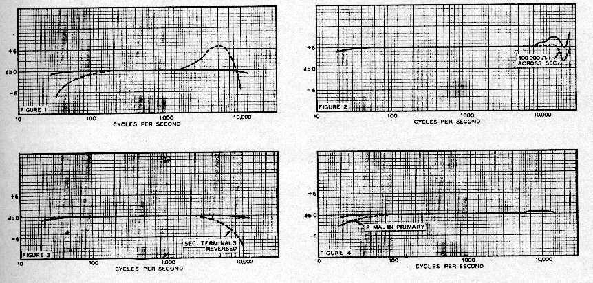
In figure 1, the solid curve represents the frequency response of an "ideal" transformer, "ideal" signifying either a theoretical design or an actual sample measured under such conditions as to give a false indication of its performance. The dotted extensions represent exaggerated departures from the "ideal" as are often encountered in practice.
High-Frequency Response
Considering the high-frequency response, a pronounced peak,
such as that indicated, is due to resonance between the leakage inductance
and the distributed capacity of the windings. This condition may
become aggravated when the unit is used in conjunction with a tube having
low plate resistance. It is essential, therefore, that the response-curve
data be taken under actual working conditions. Uniform response at
the higher frequencies is essentially a matter of design, however, and
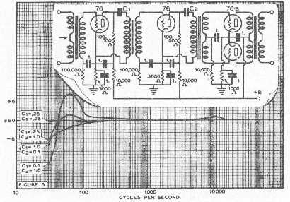
the resonant peak may be flattened out by shunting a resistor of from 250,000
to 100,000 ohms across the secondary. Figure 2 shows this. The response
becomes more nearly uniform at the expense of a slight amount of gain.
A factor having a very pronounced effect on the high frequency response of an audio transformer is the polarity of the secondary winding. In figure G the dotted curve shows the effect of reversing the connections to the secondary of a certain transformer. This transformer had its primary wound next to the core with the start connected to the plate of the preceding tube. The finish of the secondary (wound over the primary) should connect to the grid of the following tube. This assists in keeping the by-passing effect of the capacity between the two windings as low as possible.
The better grades of transformers manufactured by reliable concerns
are generally flat within one or two db up to at least 10,000 cycles. It
is essential that the individual units have as small a deviation as possible,
preferably less than one db, as the deviation is generally accumulative;
a two stage amplifier having an input, interstage, and an output transformer
each down one db at a given frequency, would have an accumulated drop of
three db.
 It might be well to add a word of caution regarding the interpretation
of gain or loss ratios in terms of the decibel. The writer had occasion
to track down a matter of five watts missing from an expected total of
thirty from the output of a certain amplifier. The "insertion Ioss",
(a factor seldom mentioned by the manufacturer) of the
output transformer amounted to approximately .95 db. This represents
a voltage loss of but 10%, but in terms of power, 20%, which could hardly
be called negligible in any case.
It might be well to add a word of caution regarding the interpretation
of gain or loss ratios in terms of the decibel. The writer had occasion
to track down a matter of five watts missing from an expected total of
thirty from the output of a certain amplifier. The "insertion Ioss",
(a factor seldom mentioned by the manufacturer) of the
output transformer amounted to approximately .95 db. This represents
a voltage loss of but 10%, but in terms of power, 20%, which could hardly
be called negligible in any case.
The "Lows"
The low-frequency response is primarily determined by the primary
inductance of the transformer. To secure high values of primary inductance,
various high permeability alloys may be used in the core. These core
materials enable the manufacturer to build compact units with remarkably
flat response over the audio spectrum. When using such units, certain
precautions must be observed in order to obtain the desired results. The
magnetic properties of the core material undergo marked changes when subjected
to mechanical shock or excessive values of flux density. They are
not suitable for applications exposed to heavy vibration, jars, etc.
Definite limits must be observed in the amount of flux generated in the
core material by the d.c. flowing to the tube.
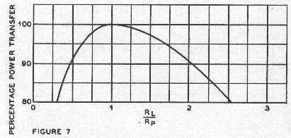
This factor limits applications to those involving small values of d.c.
or to push-pull units with balanced currents in the split primary. Parallel
feed to the tube plate through either an inductance or a resistor is often
used to eliminate the effects of the d.c. in the primary. In figure 4 is
shown the response with and without d.c. in the primary of a typical interstage
unit.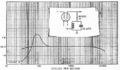
In conjunction with the parallel feed it is often possible to
utilize resonance in the primary to obtain a flat or a rising low frequency
response. The desired result is secured by using a blocking condenser
of the proper capacity in series with the primary. Figure 5 shows
a three-stage amplifier and the variations in response afforded by changing
the blocking condenser values.
Similar effects may be obtained by inserting resonant circuits
in the parallel feed to the tube plate. Such arrangements are
applicable to resistance coupled amplifiers as well. In figure G
the dotted line gives the rise in bass response due to the resonant circuit
shown.
Various other combinations have been used from time to time to provide
variations in response for specific applications.
The selection and application of transformers depends upon the particular installation under consideration; however, there are certain facts and precautions that apply to any installation and they should be kept in mind. The audio transformer is essentially an impedance adjusting device. As such, its constant must necessarily be varied according to the needs of the specific circuit. There is, nevertheless, a certain amount of leeway in the value of the constants which is often disregarded. The loss due to a mismatch in impedance between a tube and its load is shown in figure 7. This curve holds when greatest power transfer occurs with R = rp,. For greatest undistorted power output, i.e. R = 2rp, a similar curve applies. (See Radio Engineering, by Terman, page 165.) From figure 7 it is evident that between the values of one-half and twice the optimum, the loss is ten per cent or less. In the case of R = 2rp, the curve indicates power transfer variation with practically constant percentage harmonic distortion. For example, an output transformer designer to work between a tube and a 500 ohm load could have the load value varied between 250 and 1000 ohms with not more than ten per cent power loss due to mismatch. The harmonic distortion, however, would vary.
In sound reproduction for talking pictures, it is current practice to mismatch the output stage to the voice coil as much as four to one. This provides electro-dynamic dampening without adding inertia to the moving parts. The result is to prevent over-drive on powerful bass notes.
For installations subject to abuse and manipulation by careless operators, the high silicon steel core is preferable. The nickel-iron alloy core must be handled carefully after as well- as during manufacture.
Trouble may occasionally be encountered due to reversed or misplaced
terminals, or a
faulty transformer diagram. A continuity meter will enable the technician
to spot the various terminals. Sectionalized windings may he
phased out by applying a low value of a.c. voltage from the light mains
and checking for tile series aiding connection with a high-impedance voltmeter.
*611 No. Santa Anita Ave., Burbank, Calif.