| Chapter 8
Update November 2003
Necessity is the mother of invention.
What do a windshield washer hose and an old RCA public address system
cabinet have in common? Both are now part of WB2SYQ's Collins 21E .
There's been lots of tinkering, wiring, testing and
substituting since we last checked on the progress Norm's been making with
the 21E. Rewiring is nearing completion and some marginal and
non-functioning components have been identified and replaced. Various
decks, including the 300J
exciter (shown in Chapter 5) are cleaned and back in their cabinets.
Assisting for the past few months has been John Flinn, N2NOL, an EMI
engineer who works with Norm.

The problem of how to use the transmitter's original three phase final
stage power transformer, discussed in Chapter7, was resolved when the W2ZM
sale (memorialized in the AMFone.net Photo Album pages) yielded a single
phase, 3.3
kva multi-tap transformer.
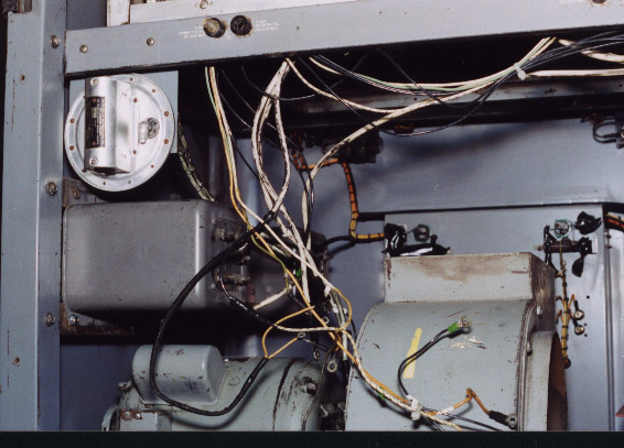
It will be recalled that the three phase power transformer was originally
meant to be housed in a metal cabinet that resembles a steam radiator
enclosure. Opting for accessibility, Norm decided to place the "new"
piece of final iron in a large, black crinkle cabinet that began life as
home to a RCA public address system. The accompanying photo also shows a
large, 240 volt, 28 amp
variac mounted on the back wall of the cabinet above the transformer.
The transformer cabinet, resting on a wooden platform similar to the one
that keeps the 21E cabinets off the concrete floor, sits about three feet
to the rear of transmitter power supply cabinet. A length of floor level
conduit containing the high voltage wiring will run from the transformer
cabinet to the base of the 21E's power supply cabinet.
Around 40 inches in height, the old RCA cabinet is an ideal
height for holding a manual and other
material, lectern style, during work.
Prior to mounting the power transformer and the variac in the RCA cabinet,
testing had to take place. The transformer primary is 240 volts and the
secondary, although not center tapped, offers a choice of three taps:
1,450, 2,080 and 2,900 volts. As designed, to produce 1 kw out the
transmitter final needs 2,500 volts at 750 ma of plate current. This is a
good starting point for calculating the power requirements for amateur
use.
The way the variac was tested to make sure it was capable of handling a
sustained current level was ingenious. Connecting the variac to the
household service, Norm dialed it for about 120 volts and connected a
toaster oven and a broiler to the variac's wiper and common end. Turning
on
the power and the appliances, he let things sit for a
while. The combined load of the two current hungry appliances showed that
the variac was up to the task of handling the load the plate iron will be
subject to during transmissions.
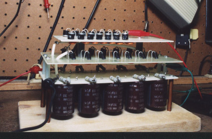
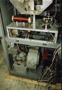
A departure from the original design of the 21E was the decision to
replace the mercury vapor rectifiers with a sturdy homebrew bridge
rectifier to be mounted in thepower transformer cabinet. While
aesthetically lesspleasing than the purple glow of hollow state
rectifiers, the solid state bridge will provide a level ofdependability
and stability that argues for its use. The rectifier tube sockets remain
and the tubes, though no longer functional, can still be placed in their
sockets so there will not be a void when one looks through the window in
the 21E's power supply cabinet.

The four diode stacks in the bridge rectifier are mounted on two boards.
The two stacks on the top board came from a 3 kv power supply for a linear
amplifier that Norm was building with the late Eliot Taylor, K4EJT. These
are rated at 1,000 PIV, 6 amps. Because Norm did not have enough of the 6
amp diodes to construct the other two legs of the bridge, he put together
the bottom stack with 1,000
PIV, 3 amp diodes wired in parallel. Beneath the bridge you can see the
filter capacitors, ten 390 uF, 350 volt caps wired in series to produce a
value of 39 uF at 3.5 kv.
|
|
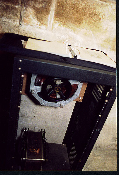
The blower, cleaned and working, has been bolted to the bottom of the
21E PA/modulator cabinet. It has yet to be mated with the flange that
funnels forced air to the deck that houses the pair of 3CX3000 modulators
and the single 3CX2500 final.
When the transmitter was in service at WEBO air from the blower was
directed to the deck through a short section of sheet metal ductwork. The
metal duct, however, was damaged during disassembly and a replacement must
still be fabricated.
Interestingly, a photograph in the 21E manual
shows the original duct between the blower and the
modulator/power amplifier deck was made of what appears to have been some
kind of cloth.
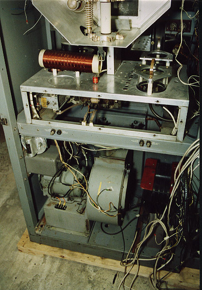
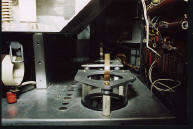
The modulators and final sit in sockets recessed beneath the deck. Air
from the blower flows past the base of each tube and up through the holes
in the deck in which the tubes are positioned. To maximize cooling, the
ceramic tubes are enclosed in glass chimneys that sit flush with the
deck. Rubber gaskets fitted to the base of the chimneys prevent forced
air from leaking out between the chimney and deck thereby assuring that as
much cooling air
flows around the tubes as possible.
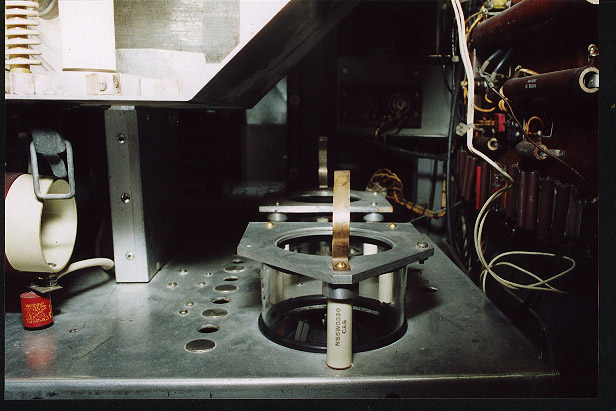
The original chimney gaskets had deteriorated so Norm decided to make new
ones. He cut lengths of rubber windshield washer hose to match the
circumference of each chimney. A slit was then made along the length of
each hose and the base of the chimney was seated in the slit. Voila,
replacement gaskets!
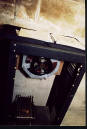
As a protective measure, Collins attached an air switch to the blower,
visible in the photo at the upper left corner of the blower. If the
blower malfunctions while the transmitter is operating, the air switch
shuts down the transmitter. This prevents further overheating and
potentially some very expensive damage. Remember that several years ago
each of the 21E's rebuilt ceramic tubes
cost $400. A spot check of the present market shows prices for new
Chinese-made replacements nearly double that figure.

After firing up the blower and hearing the noise it made, it was clear
that having the operating position anywhere near the transmitter would not
be a good idea. Norm has decided that after troubleshooting and initial
on air testing, the 21E's operating position will be in his second floor
shack.
At the spring 2003 Timonium hamfest, Norm picked up a nice Harris Stereo
80 solid state broadcast console to use with the 21E. The Stereo 80
awaits its new task while the Gates "Producer", shown in Chapter 6, has
gone to another owner.
Remote operation details are not completely worked out at this time, but
among other things use of a closed circuit TV system to monitor the
transmitter meters is planned.
An example of how CCTV is used for this purpose is depicted on
Jay, N3WWL's website.
http://home.epix.net/~n3wwl/n3wwl1.html
Jay uses a simple CCTV setup to keep tabs on the Raytheon RA-250 which is
located on the first floor of his house, while operating from his second
floor shack.
Although the 21E will not be ready for this year's Heavy Metal Rally
(December 27-28), a tentative target of spring 2004 has been mentioned
for its debut on 160 meters.
Stay tuned!
Paul, K2ORC
Back ECS Next
Home |