
Issue #114 (Web Version)
![]()
160 M. AM Window Under Fire
160 metres has long been a favorite spot for AM operation during winter evening hours because of its lack of congestion and reputation as the "gentlemen's band." In mid-evening when the QRM is several layers deep on 75, wide-open spaces are often available on 160, sometimes allowing QRM free AM reception using 5 to 10 kHz bandwidth at the receiver. Deliberate interference, rudeness and other typical 75-metre shenanigans have been rare on this band - until this season,
One evening recently I was working a station in Atlanta, on the "AM Window" frequency of 1885 kHz. Our QSO had been in progress for over a half hour when a group of SSB stations started up only 2 kHz above our carrier frequency. Although the sideband splatter was annoying, we continued our contact without interruption until we were ready to sign. Then, I decided to listen in the SSB mode to find out who was causing all the racket. I heard a group of SSB'ers bitterly complaining, whining and moaning about the "AM QRM". I checked the rest of the band, and found it nearly empty from 1880 to well above 1900 kHz. With the band nearly unoccupied, these lids chose to start up only 2 kHz away from an AM QSO, and then proceeded to gripe about the QRM!
These stations all have new style callsigns, and none are listed in my 1990 Callbook. They made frequent mention of their "11-metre days," and their style of operation was reminiscent of CB, complete with exaggerated southern accents and obvious pride in their ignorance, The most comical moment came when a couple of these amateurs demonstrated their technical expertise. One was complaining about how "wide" AM carriers are: our AM QSO was on 1885 kHz, but we were "throwing our carriers" all the way up to 1888. Another agreed, adding that he just couldn't understand why anyone would want to run AM on the ham bands, knowing that those carriers are so wide! Then came the punch line: "...the station in Atlanta is running pure AM, but the Tennessee station is running AM and SSB at the same time, I don't know how he does that, but I'm pretty sure it's illegal..."
Incidents like this are heard regularly on 75, and now the phenomenon appears to have spread to 160. A disturbing trend has developed on the amateur bands: a group of operators picks a frequency and declares it private turf. When they find the frequency already in use, they start up anyway, steadfastly refusing to change sidebands or QSY to another part of the band. Understandably, newcomers to 160 may not be aware of the longstanding "AM Window" widely recognized throughout North America in the vicinity of 1885 kHz. However, some SSB operators have recently been heard boasting that they do not intend to QSY even when the frequency is in use (by AM'ers), and that the AM window at 1885 "no longer exists." Since this incident, I have noticed several such arrogant groups scattered across 160. This isn't surprising, since with the lower sunspot count, 20 metres is dead in the evening, 40 full of foreign broadcast, and 75 congested to the hilt, so more hams are discovering 160, which is now included on all commercially built equipment. At times, 160, like 75, is so congested all the way up to 2000 kHz that it is difficult to find a clear spot to operate.
This incident stresses the importance of maintaining our AM window frequencies below 1900 kHz. Many AM'ers choose to operate in the top half of the band specifically to avoid the worsening SSB QRM, which is less severe towards the high end. But future amateur use of 1900-2000 kHz is uncertain, since amateurs are allocated these frequencies on a secondary basis, radiolocation beacons taking priority. Expansion of radiolocation could severely restrict amateur use of these frequencies, or even drive us off this part of the band entirely. We must maintain the AM window below 1900 kHz; if we abandon this portion of the band now, it will be much more difficult to re-establish AM operation there in the event we lose the top half sometime in the future.
We will maintain the AM window frequencies only if we use them regularly when we find them available, thus making sure everyone remains used to the presence of AM signals in the vicinity of 1880-1900. It is in our interest to keep our own operating practices above reproach. We don't "own" these frequencies and we don't want to become guilty of "lid" tactics ourselves, tarnishing the image of AM'ers in the minds of other hams. If a group of "sea-bears" is already on frequency before we begin, it is best to simply find a vacant spot and operate somewhere else.
Dave Sumner, K1ZZ, addresses this subject on page 9 of December QST, in an editorial titled "Expectations." He points out that in amateur radio no one is guaranteed a clear frequency. An otherwise legal transmission that happens to cause interference as a side effect is legal. Interference is a fact of life in amateur radio, always has been, and probably always will be. A lot of what annoys people on the air is not illegal. Deliberate interference is illegal, but it is hard to pinpoint because that requires a determination of intent; about the only way to do this is to change frequency and see if the offending station follows.
Wishing you a happy New Year, I'11 be looking for you on 1885.
-K4KYV
![]()
Letters to Westlink Report
ORACLE Disputed
A recent issue of Westlink Report (October 27) provides a rather clear indication that establishing a No-Code HF license in the US is not yet a reasonable alternative to any suggestions thus far proposed. Author Vernall, in explaining ORACLE's purpose, states (page 6):
"We are firmly against the lowering of standards, and would not support the 'slow code' lobby as that is tantamount to lowering standards. We want to hold standards, and also want new tests or examinations that are equally as challenging as the existing code tests..."
USA amateurs should be aware that the technical examinations in other countries...have not been lowered in standard...Examination questions are not part of a published pool...But if any amateur examination system could be said to have been 'dumbed down,' then the current USA methodology is a candidate. But presumably it could be 'undumbed' if there was a need (my emphasis added).
Therein lies the flaw in ORACLE's argument. Exams can't be 'undumbed,' at least not in the US. Once a deregulatory policy is established, returning to the former policy, i.e., restoring standards, is virtually impossible, and no major decision-making policy concerning the Amateur Radio Service has ever been made along those lines in this country. The problem turns out to be a legal one: once the barn door is opened towards easing of a requirement, any attempt to return to former standards generally will attract a cry of "discrimination," "elitism," and eventually, a lawsuit. While a No-Code HF license might be attractive to other countries where technical exams haven't been tampered with for the most part, the No Code HF license cannot work in the US, simply because technical exams for the most part no longer exist, having been pared to a condition where those at even the Extra Class level can't apply Ohm's Law. And meaningful exams will not be restored. The FCC doesn't want it, as they made clear in their refusal to discuss petitions RM-8259/60 last year, which called them to task on this very point. I see no evidence that the ARRL wants a restoring of standards either.
Under these conditions, it's difficult to understand how the ORACLE group can claim that a "slow code" proposal would lower standards, whereas a "No-Code" proposal would not! If ORACLE can exert its influence in restoring technical exams to the level they were in this country 30 years ago, then it would seem we could take the next step. As it is, we can't.
The second part of the problem concerns government's accountability in this matter. It would stem logical that the licensing process for obtaining a federal license to transmit electromagnetic waves anywhere around the earth should be a federally-based task, not a task for volunteers. FCC, in attempting to frighten hams in the late 1970s, informed amateurs that they had better run the exam process, because FCC was not going to do it. At that point, it was the duty of the national organizations in this country to inform the FCC to do its job. Failure to do so has presented us with a process that adds nothing to our credibility as a Service.
VEC's in this country for the most part have done a good job in conducting exams, despite the fact that the technical "exam" is no longer, owing to the fact that questions and answers are published beforehand. However, the reported accounts of fraud in the system have been too frequent and widespread to ignore; government should long ago have stepped in to reclaim the function they should be doing, but they haven't, indicating that FCC is not concerned about what we do, just as long as we don't occupy any frequencies of any commercial worth. Easing of requirements, and fraud, have weakened our position in any case for those frequencies. We have become just another group of hobbyists, not a technical hobby justifying our frequency allocation.
Restore examination standards, and demand that government perform their job in running, restoring, and enforcing the standards of those exams, then perhaps one can begin to speak of a No-Code HF license in this country, otherwise amateurs can't afford to back down one inch on the easing of standards. One needs only to look at history to understand that as we continue to deregulate, we lose frequencies.
"The code issue has Llittle to do with whether it gets through when other modes do not, whether it is a useful mode or not, or whether new hams should 'pay their dues' as their predecessors. The issue is whether this Service should tolerate a further easing of requirements, both code and theory, to save a hobby that, under the circumstances, might not be worth saving. The issue involves deregulation, pure and simple, and it will be a durable beast."
-Former ARRL President Vic Clark, 1982.
Regards,
Vince Biancomano, WB2EZG
Life Member, ARRL
EDITOR'S NOTE: This letter appeared in the December 16 edition of Westlink Report. We have used this amateur radio newsletter as a source of information ever since AM P/X began publishing. It is with regret that we recently learned that Westlink has ceased publication and the last issue was sent out in January, 1995. The two other mainstream amateur radio newsletters remaining are the ARRL LETTER and W5YI Report, which we frequently quote as news sources.
![]()
HOMEBREW AM CONTEST
3773 CONCESSION ROAD 3
RR #8
NEWCASTLE, ONTARIO L1B 1L9
CANADAIt saddens me to report that response to The AM Press /Exchange "Homebrew Contest" has fallen far, far short of expectations: as of this writing (23rd September 1994), I have received but one single solitary entry!
My own personal attraction to the AM mode initially was due in no small part to the fact that the majority of AM'ers appeared to be among the last stalwarts in Amateur Radio still proudly toiling away on the homebrew front. Has this changed? Do we, too, now celebrate the merits of "appliance operating" (albeit with appliances hailing from the 40s, 50s, and 60s) as opposed to rejoicing in "...rolling our own"?
I absolutely KNOW that there are scores of classic tinkerers and experimenters, in the finest Amateur Radio tradition, churning out interesting - and diverse creations from basement work benches all across the continent. How about sharing your experiences with others through the pages of The AM Press/Exchange? Special writing skills in this regard are most absolutely NOT a prerequisite! Just jot down a few handwritten notes, rough out a block diagram, take a few clear snapshots...and let me do the rest.
It's not too late. Besides, the deadline for entries can always be extended contingent upon reader interest. So, how about it? By sharing your ingenuity with fellow AM'ers, you just might inspire some latent, would-be homebrewer amongst us to pick up the gauntlet, and maintain a proud and noble heritage within Amateur Radio for yet another generation!
73, de EDWARD "EDDY" PETER SWYNAR, VE3CUI
EDITOR'S NOTE: Eddy has extended the deadline for entries one year. Formal contest entries must be received no later than 31 December, 1995. The winner will be announced at the 1996 Dayton Hamvention AM Forum, Following is an "ineligible entry" submitted by the contest chairman to serve as a sample article. For full details on the contest, see AM P/X issue # 111, page 2.
![]()
Homebrew AM Contest
Ineligible entry Eddy Swynar, VE3CUI
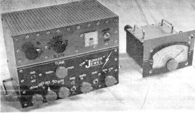
As contest chairman for The AM Press/Exchange "Homebrew AM Contest", I declare myself ineligible (obviously) for the receipt of any award with this "...off the-record submission"; still, the "Junker Jewel" continues to be a source of considerable pride to, and is a welcome addition at, Amateur Radio station VE3CUI. It is a degree of shameless immodesty, I must confess, which compels me to share information on my flexible little rig with the readers of AM/PX...
This 12-watt, three band, band-switching AM/CW transmitter is a "junker" in the truest (and most affectionate) sense of the term. Nothing was purchased '...brand new’: each and every component---including the chassis and aluminum covers---was acquired via the junk box/Hamfest/surplus re-cycle route (it may interest friends of VE3HC to know that the modulation transformer is an N.0.S. unit manufactured by the Hammond Company some years ago, and purchased at a flea market for $2.00).
Frequency control---internal crystal oscillator, or external VFO---is selected via a switch located on the rear panel; likewise, a similar nearby toggle allows for two options while keying in CW, i.e. 6AG7 oscillator/2E26 amplifier cathode keying, or grid block keying (minus 15 volts on the 6DT6 suppressor grid) when using the VFO.
With 5-minutes of warm-up time (and with no temperature compensation whatsoever), the VFO drifts downward by 130-cycles during the course of one hour on 160-meters (better than my stock Ranger-l!). In spite of the problems one right associate with tapping close-wound coils, I have found the Hartley oscillator to be much more user-friendly for the experimentally inclined, than the Colpitts (fewer capacitors).
Note the use of gears in the VFO: after it was built (naturally!), I found its tuning range (with a single 0-140 pfd. air variable capacitor), to be too limited for complete coverage of the three bands (160, 80, and 40-meters) for which it was designed. There existed just enough space along side this capacitor for a second 0-100 pfd. Hammarlund midget---but in order to retain "single knob" frequency control, I had to gear-couple the rear shaft extensions of the variables (both gears, including a smaller, center pinion gear, are from junk automobile odometers). Backlash with such an arrangement was inevitable, but I have not found it to be overly objectionable.
The 2E26 final RF stage runs at about 300-volts/40 ma. input---not as much as I would have liked when using the rig as a driver for my 2x813 grounded-grid linear, but still good enough for 100-watts of carrier output on 75-meters when coupled to the amplifier. Inspiration as to the circuit parameters used in the various stages of the "Junker Jewel" was acquired primarily via the first (1963) edition of the ARRL's Understanding Amateur Radio, the premier (1955) edition of Newington's The Mobile Manual for Radio Amateurs, and the 1962 and 1969 editions of the League's Handbook. I simply borrowed ideas from various designs and layouts that I liked, then "...mixed and matched" to achieve the end result.
The audio and keying both of the rig sound quite good, by all accounts. I was somewhat hesitant to speak into the microphone at first, not knowing what to expect (having never before built a complete, bonafide plate-modulated transmitter)...but common sense planning and parts arrangement of the audio components beforehand paid-off in clean, balanced audio, with no hum or feedback...
Likewise, the rig is "clean" with respect to harmonically-generated RFI in that all power leads from the external supply entering both enclosures (and the meter shield) pass through individual Pi filters consisting of a feed-through capacitor, a disc ceramic bypass capacitor, a small inductor, and then a second disc ceramic bypass.
To conclude, I feel that the "Junker Jewel" has, for the most part, lived up to personal expectations performance-wise---and it looks good sitting atop the operating desk, being not too shabby in the appearance department either! There exists no greater way to acquire practical knowledge in electronics than to build your own radio, whatever the complexity. This rig has simply re-affirmed my conviction in this regard, as I proudly preface my AM QSOs with the comment, "...The transmitter here is 100% homebrewed, old man". Period.
Edward "Eddy" Peter Swynar, VE3CUI
(click on the items below to view illustrations)
- Fig. 1. Block diagram of the "Junker Jewell"
- Fig. 2. The "Junker Jewell" combination, less about 100+ sheet metal screws used in the suppression of RFI, etc.
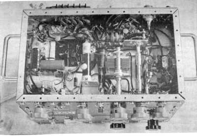
- Fig. 3. "Busy or what?" Audio parts (left), center coil/cap is driver tuner. Bandswitch near rear. Oscillator is on right-hand side (see ceramic trimmer). Note RFI filtering below terminal strip. Grey knobs are simply black plastic with spray paint.
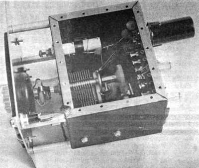
- Fig 4. One of 2 air variables; small air variable at the rear (below tube) is trimmer/adjuster. Coil is brass slug-tuned ceramic core wound with #29 enamel copper, tapped 1/3 from cold end. Case is steel utility unit acquired for $3.00 surplus.
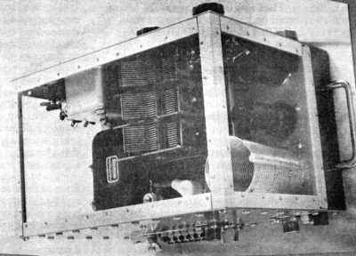
- Fig. 5. Final Pi-Tank coil and loading cap. Also visible (left) is modulation transformer. Right, is 6AG7 osc/buffer and 6DT6 keyer.
![]()
MAKE A STATEMENT! Be the hit of the hamfest, or your local radio club meeting with this DARING T-Shirt that pulls no punches and SAYS IT ALL!! "I HATE SLOPBUCKETS" in bold, black, block letters is emblazoned across the chest. Just below that, in brilliant florescent yellow "with really neat sparks", is "AM FOREVER." Quality Fruit of the Loom made in USA. Available in gray, red, blue, and green, in sizes M, L, XL. Just $15.00 ppd. Make check or MO payable to "Hate Slopbuckets." (Address excluded because past issue.)
![]()
LIGHTNING STRIKES AGAIN
THEN I PUT UP MY SKY BRUSHESNOW I CAN HEAR IT LEAKING OFF THE ENDS
MY S METER SHOWS THE VOLTAGE BUILDUP UNTIL THE BIG BANGby George A.H. Bonadio, W2WLR, 373 EAST AVENUE, WATERTOWN, NY 13601-3829
THIS LAST ONE WAS A BIG STRIKE
It hit the whole neighborhood in one big flash. It was a weekday in early August and our TV was on. There were lightning strikes around. I was walking between the TV set and the window. There was this characteristic lightning click on the sound.
I knew what it was and I looked out the window as the whole house shook in the blast. A hundred feet away I saw burning embers drop from that tree to the ground. Our TV went dead, but power stayed on.
It took out the automatic controls on the two nearest street corner lights. It took out at least 5 TV sets, several VCR's including ours. It killed my FAX power supply. It ruined my answering machine and another in the neighborhood. My remote telephone quit, as did others.
About three months later I find that my battery charger lost both of its 30 A 200 V rectifiers. That was the pick up on 16 feet of # 16 zip cord on hooks on the garage wall.
"YOU SHOULD HAVE HAD BURIED SERVICES, GEORGE!"
I do have. The power, 200 A service, and the dual phone lines are buried apart for 75 feet. The TV cable is 125 feet underground.
Both neighbors on both sides of me have theirs buried and they lost practically everything, also.
When a bolt of, say, 40,000 A strikes in the area it excites many opposite surges. A one tenth of one percent of that in an induced surge could have been 40 A at great voltages to take out my battery charger diodes.
The damage came through the air, and was not conveyed along buried power lines, past my surge protectors, past my 1600 V caps in my switch box with its #2 grounding bus to my one inch water main.
"WERE YOU COVERED BY ENOUGH INSURANCE?"
After my $100 deductible I still received over $900. I had the "replacement value clause" on mine. But I don't want to go through that again. This was the fourth time that we have had some lightning damage in our 37 years here.
LIGHTNING ARRESTORS VS. LIGHTNING BRUSHES
I have examined barn lightning arrestors for a lifetime. They have massive grounding systems with twisted #0 square buss up from the ground, across the roof and back down on the other side. There are usually four spikes rising from the top run of copper the size of your thumb.
Lightning still takes down some of these systems with a real fire. It is not satisfactory. There is a better way. We, now, brush it away.
SPARK GAP STUDY
We have all seen photos of power company spark generators. They develop tremendous voltages between huge and smooth surfaces, often spherical. They have no sharp edges to leak and start a spark.
The brush theory is that Saint Elmo's Fire on wet masts of sailing ships at sea, in a storm, were leaking off from wet ropes, pole ends and various metal fixtures high on the ship. Without these leakages all of these ships would have been struck several times in every storm, especially if there were no other ships for miles around. This would have been a great deterrent to sailing far from land.
St. Saint Elmo's Fire probably drained from more than ten ends on the typical sailing ship. The wetness would have been conduction from previously salt water wetness and new salt sprays of a raging storm. A single mast might be more dangerous, not leaking enough current.
MODERN LEAKING BRUSHES ON TOP OF COMMERCIAL TOWERS
There are at least two companies selling sharp ended brushes for leaking the current of the earth into the sky to drain the demand for a spark to relieve the high tension. One sold sturdy brushes of 125 stainless steel needles on mounts for three to be on the three corners of the top of the 985 foot tower. My 2 meter antenna was halfway up, with 8 elements spread over 44 feet.
Before they were installed I was working in the repeater shack ten feet from the base of the tower. One horrendous bang. The guy wires took it all away. All except what went through my kidneys. They were relaxed for a while.
Another company has smaller wires on its brushes. They claim thousands of sharp ends in about two feet of length.
They are in error. They sell grounding wire of huge sizes and expensive copper. Then they sell a tuner bypassing choke of so many hundreds of turns for the DC continuity and make the choke out of # 18 wire.
TIME VERSUS CURRENT FACTOR
One experimenter, with new brushes on the top of his broadcasting tower took his opportunity. (He must have been a ham.) His tower was free after midnight and a storm was approaching. He wired in a DC meter in series with the tower to the ground. The storm came.
He claimed that his meter read about two A for about ten minutes of the peak of the storm. There were no strikes nearby that night. If a 40,000 A strike lasts 1/100,000th of a second, that much power would be represented by 0.4 A for one whole second from that same voltage source.
He may have dissipated several strikes in the immediate neighborhood while he read his meter. Your guess is as good as mine. He did not need #0 buss bar to conduct 2 A of DC. That # 18 wire would have been fine.
The point is that the old lightning arrestors were designed to direct a strike into its grounding system at a minimum of damage. The new brush design is to leak off the building charge. We do not need larger than a # 18 (say) electric fence wire to the earth. Yes, it could go through a choke, but that choke could accept a charge miles away and develop considerable voltage across it.
IT JUMPED 4" TO THE GROUNDING
I was showing Carl, W2VUH, my antenna tuner on my 400 foot long, 40 foot high antenna. Lightning hit the City hall tower and destroyed its flagpole. It jumped across 4 inches in my tuner to ground, and both of us saw it. We timed it, and it agreed with the flagpole one and a half miles away.
I HAVE PUT UP THREE BRUSHES, SO FAR.
One is on my lower TV antenna for Canada, and two are on the two 35 foot pipes for my B2D antenna on my house. You can order them from your construction contractors wholesaler.
They are from SCHAEFER BRUSH MANUFACTURING; FLUE & CONDENSER BRUSH; #43,568 SINGLE SPIRAL STAINLESS STEEL ROUND FLUE SIZE: 4 1/4" BRUSH DIA: 4".
My local supplier said that he would be glad to send you the first one for $25 and extras, in the same order for $15 each. They are McQuade & Brannigan Inc.; Bradley St. & Commerce Park, Watertown NY 13601 The brushes are strong and bottom in a fitting to screw in an iron pipe of 1/4" i.d. (inside diameter) for mounting. You will need a foot or so of 1/4" i.d. one end threaded pipe and two 100% stainless steel hose clamps for each. Designed lightning brushes go for $125.
Handle them with gloves or you can become all bloody. Those ends are jagged and perfect for corona leaking and for stabbing your hands.
MY FIRST STORM TEST WAS INTERESTING
My B2D antenna was on 75, through my tuner into my 1950 75A2 Collins receiver. Thunder was heard and lightning was seen. Power on, antenna switch off of grounding to 75. Characteristic "snow static rapid popping noise" was heard in summer !
S meter rose slowly from 3 to over 9. There was a click of lightning with a distant strike and the meter was down below 3, but on the way up again. By now I was standing back, clear of all innocent fixtures like mikes, etc. and was very high strong.
The storm came in closer and the meter moved faster. The snow static noise became higher pitch and there were strikes which were within a mile of here. Less than five seconds of count as the sound arrival is under a mile. I opened a window a little.
Apparently my set was hearing the corona discharge from my busiest antenna brush. It is only about a foot from an antenna end on each of two poles. Becoming bolder I took a well insulated screwdriver and filled the gap between the antenna coil and a grounded member.
I could both hear and see the small spark each time. The antenna was having its own floating voltage above the ground. Then I concentrated on the time factors. What am I hearing ? Where are these voltages developed ? Is there a neutral ? How far are charges carried ? What can I learn ?
THE BIG, BIG EARTH IS ON ITS OWN
There, obviously, is a charge developed between the earth and a cloud. This gracefully develops great voltage gradients for elevations above the ground. With very little leakage these voltages will exceed any voltages which we can make.
However, the breakdown of insulation eventually happens and the voltage difference momentarily disappears. New charges build a new voltage, and this may go into another strike. This is what I saw happening.
However, there was a surprise. I was seeing meter swings suggesting continual building and discharging of voltages. These were, apparently, all in the same polarity. Further, I was seeing voltage buildups which were dissipated by lightning at least two whole miles away.
For build up current of only a few amps the resistance of the earth, from here to there, is insignificant. The surface might just as well be a huge sheet of silver. The voltage under a cloud, just before it strikes, must be all-alike because any modest current will develop no significant voltage in this low resistance surface of the earth.
PEACEFUL, INNOCENT EARTH
The earth surface resistance between any two points miles apart is substantially the same as even much farther apart because of the paralleling of resistive paths by the millions. Thus, before a strike, the earth has no surface developed voltage for two reasons. There is so little resistance, and there is so little leakage current. It is everywhere alike.
It is only the fraction of a second of heavy current which develops some voltage in the surface flow. This voltage will, of course, be lost with all the strike current induced voltages in trees, houses, wirings, plumbing, pieces of metal, utility circuits, wet clothes lines and on and on.
Thus, it is the clouds which develop voltages, independent of the earth. This is why we have some lightning storms with many bolts but none of them hitting the earth. Every few years, here, there are reports of one bolt, which does not hit the earth but which shakes houses below it for as much as twenty miles. These seem to be snow clouds. If you are near one end the instantaneous discharge is heard for as long as a minute as it arrives from so many miles away.
PUTTING YOUR BRUSHES UP
The protection area around an old fashioned spiked top arrestor was estimated at five feet out for every foot down. In other words, your arrestors would not be expected to help your neighbors unless they were close to the ground.
Modern brushes, however, we believe, drain charges so that there is less charge over you. This cone of protection is presumed to be larger and more effective, particularly in preventing a strike, rather than channeling a heavy strike to ground through a heavy conductor.
The brushes actively participate in the storm charges all through the storm, instead of just in a strike.
Saint Elmo's Fire is sometimes seen on airplane wingtips and from tree tops, and from church spires.
The color of the Fire is red when the earth is on the positive side and it is blue if the earth is on the negative side.
I believe that your amateur ingenuity can figure out what type of installation protection you need to keep draining neighborhood discharge voltages so that I can hear you on, again, after your next few thunder storms go by.
Happy brush groundings!
![]()
Loading Link-Coupled Transmitters on 160
Transmitters using plug-in coils with a variable link in the RF output circuit are sometimes difficult to load into 50 ohms on 160 metres. The reason is usually that the link coil has too few turns. This output circuit was designed, in the pre-coax days, to feed directly into a similar link at the antenna tuner, using two conductors with no regard to line impedance. Link-coupled tank coils can be found in the BC-610 (Hallicrafters MT-4), the early Globe King 400 series transmitters, and in many homebrew transmitters from the 1930's through the mid 50's. Some hams still build transmitters today using this example of excellence in classic design.
On 80, 40 and above, the link will load readily into coax line using a series resonating capacitor. This is fully explained in the transmitter section of any ARRL Handbook published in the vacuum tube era. If the link is too small, you may get some coupling when the capacitor is tuned to resonance, but the final is still not fully loaded. Sometimes the link can be parallel tuned instead of series tuned, but typically, this brings little improvement. I have never had any success with the Handbook's suggested alternative of placing a small inductance in series with the link.
The solution is to parallel tune the link using two capacitors in series, and place the load across only one of these capacitors. This allows the tuned link to operate at a higher "Q" because the load impedance is now "tapped down" to appear across only a portion of the tuned circuit.
For a typical 4 to 6 turn link, try using .002 to .004 mfd per fixed capacitor. Transmitting micas should be used. These are still plentiful from WWII surplus. Unless you can find large transmitting micas, it is better to parallel several smaller capacitors of approximately 500 pf each; to achieve the required fixed capacitance. This will distribute the rf current among several capacitors, resulting in less danger of overheating. It will also allow you to "fine tune" the fixed capacitance so that resonance occurs with the variable capacitor at approximately mid setting, The variable should be from 1500 to 2500 pf at full capacitance, and is used to tune for exact resonance. A 3 or 4 gang tuning capacitor from an old TRF broadcast receiver will work FB. (Please don't dismantle a vintage BC receiver just for the capacitor; these can be found in many junkboxes, already stripped from pre-war sets by hams in a less enlightened era.)
- K4KYV
![]()
Easy Audio Modifications for the Apache
ANDY BELL KC4FCU
Here are a few very simple modifications for the speech amp of the "scratchy Apache". After my first experience with a TX-1, I quickly made a few changes in the audio chain to improve the audio quality, and I am well pleased with the "on air" reports about my rig.
On A.M. the microphone (in my opinion) is your key to good audio quality. Stay away from the dynamic hand mics and the noise canceling type mics. These are fine on ssb, but to me they sound too mushy for A.M. If you can, choose a mic with a wide frequency range. You may have to experiment to find the one that’s right for your voice. I use a slightly modified Shure 444 which has a factory rating of 300 to 6000 cycles, with good punch in the 1000 to 3000 cycle range. An excellent choice is the old standard, D-104; and although somewhat expensive, one of the newer electret type mics with a built in equalizer adjusted to your voice will probably do fine.
My Apache had more than enough audio gain, and actually had too much for my needs. The 444 mic drove the speech amp too hard, I had to keep the gain controls almost at minimum, and only a slight adjustment would cause the rig to over modulate. In my experiments, I have found that a good audio amp likes to operate anywhere from 50 to 90% of its rated output to get the best dynamic range and distortion figures. If you have an Apache, the quickest way to reduce the gain is to replace V7 which is a 12AX7 high mu triode, with a 12AU7 medium mu triode. Both tubes by the way are dual tubes.
I still needed to reduce the gain, so by the trial and error method, I put 2 megohms of resistance in series with pin 1 of V7. This is the plate lead of the first stage of amplification in the speech amp. And of course, more resistance will drop the gain even more. The best thing to do is experiment to find the value that best suits your needs. The resistance can be inserted in the line anywhere from the tube base (pin 1) to the gain control, a 500k ohm pot located on the front panel. If you choose to connect at the gain control, connect the resistance in series with the red wire on pin 3 of the pot. This is in reference to pin 1 being ground. These modifications lowered the audio gain substantially, and gave much more headroom in the adjustment of the gain controls. It also improved the frequency response of the speech amp.
Both the bass and the high frequency ranges improved after these modifications were done to the transmitter.
The "scratchy Apache" probably got its nickname from the presence of tube V8; a 6AL5 dual diode used as a clipper circuit, and it does what a clipper does best; rolls off your bass response, and distorts your highs by clipping off the audio voltage peaks above a certain limit. This clipping action allows you to raise your average level of modulation, but with noticeable distortion level. You can simply remove the tube from the circuit and this will take care of that situation. However, with the previously described modification, the audio level into the clipper is not so high that it will cause severe clipping. In my rig, it gave just enough clipping to notice the effect, but without the distortion.
Also, replacing the 2 – 510 pf capacitors (600V mica) with a little more capacitance will give you some added bass response these caps are located in series with pin 1 and pin 6 of tube V7. If you’ve got a pretty good junk box, (or a ham friend who does) experiment with different values to get the response you like, taking into consideration the limits of your mic in the bass region.
I suggest leaving the low pass audio filter in the circuit, and for these reasons. I took it out of line in my rig, and did some "on the air" comparisons with an audio bandwidth around 6 kHz. I did not get any better signal reports, the intelligibility did not increase noticeably, but the adjacent frequency splatter did. And most of all, the high frequency audio peaks caused the modulator to work harder than necessary to maintain a respectable level of on the air audio.
![]()
FOR SALE: RCA commercial power transformers, PRI: 190-210-230-250 VAC, SEC: 3500-4600 VAC CT, rated at 1.75 KVA, asking $75 ea. The above transformers are very husky, designed for continuous commercial service and have never been used! Bruce, WXXXXX (edited out, Past Issue)