
Issue #113 -
Nov. 1994
Scanned
and OCR'ed by Grant Youngman, NQ5T
![]()
FCC Continues to Issue Fines Ruled Illegal by Court
On July 14, 1994, the Court of Appeals for the District of Columbia Circuit in a 3-0 decision ruled that the forfeiture standards used by the Federal Communications Commission are illegal.
Prior to the summer of 1991, FCC field offices were delegated the authority to impose fines of up to $2000. With little or no reported debate, Congress increased that authority to $25,000 as part of the 1991 annual appropriation of funds to the FCC. On August 1, 1991, the FCC issued a "policy statement" (FCC 91-217) which set forth new standards for assessing fines. The FCC abandoned its longstanding case-by-case approach to assessing fines against licensees determined to be in violation of FCC rules. In its place, the Commission set forth "base forfeiture amounts", which could be adjusted up or down "… depending on the nature, circumstances, extent and gravity of the violation, degree of culpability, history of prior offences and ability to pay." The FCC said that its new forfeiture schedule was intended to " ... aid our enforcement efforts by making clear in advance the likely consequences of violations."
Since the new system has been imposed, there have been complaints that the amount of money in the fines far exceeds what could be considered reasonable for the seriousness of the offences cited. Broadcast stations have been especially hard hit, sometimes receiving fines of thousands of dollars for minor technical violations or failure to properly keep track of all the required paperwork, even after demonstrating good-faith effort to correct deficiencies once station personnel became aware there was a problem. Telephone companies complained the fines were unfair because they could face a fine of $80,000 while broadcasters and cable operators would be fined only $20,000 for identical violations. There are reportedly at least half a dozen hams facing major fines. In one case, a repeater operator has been fined $7,000 for continuing to operate his repeater after the ARRL-accepted frequency coordinator deleted his machine from the list without a single word of explanation. FCC Docket 85-22 apparently grants repeater coordinators broad authority to "decoordinate."
A telecommunications organization representing telephone companies challenged the fine schedule in Court on grounds that the FCC adopted the new rules without notice and without allowing interested parties to comment. On July 14 the D.C. Court of appeals overturned the FCC's revised system of issuing fines. The Court said the FCC failed to consider public comment before implementation as required under the Administrative Procedures Act. In fact, the Court went so far as to say that the FCC knowingly failed to give all interested parties the opportunity to comment on the policy change before it was adopted. The FCC has only three possible options. It can appeal to the United States Supreme Court seeking a reversal of the decision against it; it can revert to its pre-1991 monetary forfeiture schedule and issue a Notice of Proposed Rulemaking on a new schedule of fines; or it can abandon fines altogether. It is unclear how the more than 3,000 individual fines issued over the last three years, fines yet to be paid and pending cases will be affected. Already, the National Association of Broadcasters has sent a letter to the FCC asking the fine schedule be scrapped and all outstanding assessments be cancelled. Several hams who are currently the target of FCC fines based on the Base Forfeiture Schedule are saying that they, too, will demand that the actions against them be cancelled.
Since the base monetary forfeiture amounts in all services were raised simultaneously, it was expected that all outstanding fines based on the revised rates would be cancelled or placed in limbo. But that is apparently not the case. Washington insiders report that the FCC is taking a very narrow view of the appeals court decision. While it may be unsure what it will do in regard to telephone related violations, the FCC appears to have decided that the decision affects telephone services only.
This means the FCC will probably continue to issue very large monetary forfeitures based on its 1991 revised schedule in all services not directly covered in the appeals court decision, and hams and others facing major fines will have to pay, or else take on the burden and expense of making similar appeals of their own to the federal courts.
The following opinion is excerpted from a letter to Westlink Report. The complete text appears in Issue No. 680, Sept. 16 1994, page 4. It was written in regard to the $7,000 fine assessed against the "decoordinated" repeater that continued operation.
|
![]()
Well Funded International Lobbyists Seek to Eliminate Code Requirement
Last issue we reported a plan being formulated by the amateur radio equipment industry in this country to lower the General Class code speed requirement from 13 to 10 or perhaps even 5 words per minute, for the express purpose of bolstering equipment sales by easing access to the HF bands. Mandatory Morse Code testing will be eliminated altogether as an international requirement for any class of ham radio license if an organization calling itself ORACLE (Organization Requesting Alternatives by Code-Less Examinations) is successful in its newly announced worldwide campaign. ORACLE is pushing its goal of optional CW for the next World Radio-communications Conference. The last such conference, known as WARC, was held in 1979. ORACLE is a newly conceived international organization based in Wellington, New Zealand, and holds the status of a legitimate New Zealand corporation. Its six member board of directors believes it can accomplish its objective at the next international conference.
ORACLE has stated its fundamental mission as lobbying for the modification of International Radio Article 32, Section 2735. This rule says that any person seeking a license to operate an amateur radio station below 30 MHz has to prove he is able to send correctly by hand and receive correctly by ear, texts of communications in Morse Code signaling. There is no international code speed requirement; each country is free to set its own as it sees fit. Like the U.S. lobbyists, ORACLE believes that the main reason that the Morse requirement is being retained in amateur radio is to limit access to amateur bands below 30 MHz. Its stated goal goes beyond convincing government agencies like our FCC to lower the code speed requirement; ORACLE wants the CW requirement eliminated altogether.
Rather than attempting to work with national amateur radio societies, such as the American Radio Relay League and Radio Society of Great Britain, ORACLE is bypassing them and taking its case against keeping the code requirement directly to the international regulators and communications policy makers from every nation that belongs to the International Telecommunications Union. These are the people who will make the decision at the World Radio-communications Conference whether the code stays or goes. ORACLE apparently feels there is too much pro-code sentiment in the national organizations such as ARRL and RSGB.
ORACLE's goal is to have Section 2735 modified to read: "Administrations may take such measures as they Judge necessary to verify the proficiency in the Morse Code of any person wishing to operate the apparatus of an amateur station." This means giving every nation the option of waiving code testing as a requirement for operation on any amateur frequency, including HF.
It appears that ORACLE is being well financed by undisclosed sources. The group has announced plans to present arguments for abolishing the current mandatory code requirements to the Voluntary Group of Experts subcommittee of the International Telecommunications Union at or before the next two World Radio-communication Conferences scheduled for 1995 and 1997. The address of the organization is listed as: O.R.A.C.L.E., Attention Mr. Bob Vernall ZL2CA, 90 Campbell Street, Karon, Wellington, New Zealand.
International Morse Code requirements was among topics discussed when the Administrative Council of the International Amateur Radio Union met in Singapore, September 10 to 12, 1994. A resolution concerning the requirement in the Radio Regulations for a demonstration of Morse Code ability for operators licensed to use amateur frequencies below 30 MHz was adopted. Consistent with the views of the member societies as expressed through the regional organizations, the IARU will neither propose nor support any change in the international code requirement at this time.
The IARU is an international "umbrella organization" whose members are the national amateur radio societies, which includes ARRL representing the U.S. and RSGB representing Great Britain.
REFERENCES: Westlink Report (Aug 31 issue), Newsline, W5YI Report, The Vernall Report, ARRL Letter (Sept 19 issue).
![]()
The ATC/ART-13
(Article format revised for improved web presentation. Ed.)
Mike/WA1MTZ
605 Loomis St.
Westfield, Ma. 01085
If you are lucky enough to acquire one of these fine Collins famous auto tune rigs in an unaltered state I assure the reader that putting it on the air is not a difficult process as it seems.
First I would like to mention that on of the things to do is to disregard any advice that you may come across in the "conversion" articles, as there is nothing to convert! All you need to do is to build an adequate power supply that duplicates the original function of the Dynamotor power supply. Emphasis of this article is to get you on the air with the rig and a few audio mods to improve things a bit. You can go further with audio but these are rather simple and will yield a good response.
Some of the features of this rig are …:
|
And the frequency coverage is 1975kc-18.200 mc! I have used this rig on the 17M AM window 18.150, talked with S.B. stations that did not detect any drift or fm-ing prompting them to try A.M. (made a few converts here).
Searching for info was confusing, i.e., conversion articles from the past abound with power supplies that would render some front panel controls inoperative, metering that was inaccurate resulting in operation outside of design parameters. Maybe resulting in increased RF output at the expense or insufficient modulation percentage, saturation of that little mod xfrmer and resulting audio distortion to boot! Run as intended, … it is one great work horse.
One caveat -- do not drill additional holes for cooling but rather rest the top cover open on top of a couple of 2 x 2's or hang a cooling fan on the outside by the 813 to draw the air OUT OF THE RIG NOT INTO THE RIG. Reason is that the VFO needs to get air in from bottom. The xmtr was designed for convection cooling, and a natural air flow.
[For] information, a large thick copied manual is currently available from Fair Radio, Lima, Ohio for around $14 (current price is unknown. Ed.) and is a wealth of info as well as circuit descriptions. Also includes the L.F. feature and external box for it. Also is a schematic of the ART-13B which has extended lower freq. (1650 kc) as well as an optional xtal osc. with over 24 channels. The latter only applies to the B unit but an industrious person might one day decide to upgrade the rig and the info is there. Fair Radio is currently selling these rigs again (not the B though).
Oh, just remembered … the T/R relay is the glass enclosed vacuum type. [Be] careful around it. Another feature is the built in 200 kc marker xtal osc. used to check the VFO's freq. calibration. One of the ESSENTIAL items you will need is the power connector, P-7/U plug. It has the space for the HV B+ and heavy contacts for the 28 vdc. The 2 pin plug facing towards the back is for the CV-32/U L.F. control box (tank & antenna tuner 200kc & up). It does have a keyed 28v output here. Also the multi-pin remote plug has spdt contacts on it for rx muting. You could use a couple of contacts from an old tube socket or connector with shrink tubing over the contact to utilize the mute line off the multi-pin [connector].
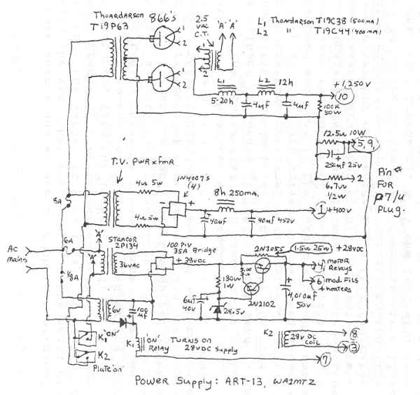
The power supply: the goal here was to duplicate the original supply. All the original front panel controls will operate as original as well as the metering. I recommend that the toggle switch labeled "Test" be changed to a standard on/off. It is wired in parallel with the PTT on the mic jack (which is less than a standard quarter inch size, and is also connected to Key and T.S. which are standard quarter inch size. The power required is +1250, +400 +28 and a small 6 vdc which I added. It's [6 vdc] sole function is to activate the AC Mains to the 28v supply which once on, will activate all other functions. The 6v supply is always "on" but a main off and main off for the HV was included for adjustments to the rig [and] safety reasons. The power supply normally is not accessed and can be placed in an out of the way location to conserve space in the shack. The H.V. supply and all [of] it's iron was fabricated on a wooden box made of 2x12 pine with a perforated metal. [It also has] front casters on the bottom and a removable wood top held in place with long drywall type screws (4). The 400v 28v 6v relays are mounted on a steel chassis measuring 8x17x2 which sits on top of the wood box/chassis [which has] 12x12x22 outside measure.
Click here to see schematic of ART-13 Power Supply
There were charts and a tune up book that originally came with the rig, that when you read the small dial near the vfo then the large vfo dial itself it would give out the exact frequency that could be checked with the 200 kc beat note from the internal calibrator and heard in the headphones. By the way, under the door that holds the tuning chart is the sidetone volume that is [a] switch that selects taps on an output xfmr. For break in operation, I patch a cord from the output (phones) jack of my rx (BC-779) to sidetone 1, and headphones to sidetone 2.
The VFO dial works sort of like this: select band 4 (in triangle) 3.6-4.0, [set] small dial at 1 [and] large dial at 45, thus 3614.5Kc. when calibrated.
Tuning up: the coarse dial C at same number as the coarse A (Band Frequency Select). [Set] the ant load C and ant tune D fine … at zero. With the mode switch in the tune position, move course C up or down for a deep dip in plate current (60ma). Then alternately use the load and tune in the normal way until you are able to reach the bottom of the plate meter marked CW place in operate. [The] meter should now go to the bottom of the scale marked MCW. When modulating, voice peaks will reach the top of the scale, as this indicates modulator current on top of DC current to the final. You should notice RF Ammeter deflection. It will vary depending on antenna impedance. A 75 ohm load will show about 1.5A. My 40m Windom shows 2.25A on 40 and … 5 amps on 75, 3 amps on 30 m (cw) for the same antenna.
When setting the mechanical presets in the memory, remember to lock the knobs before changing channels. Also worth noting; if the Ant coarse C is not properly seated you will find no plate current or grid drive.
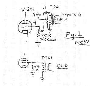
Audio mods are rather easy, as the audio driver unplugs from the chassis. Change C204 to .1[uF]. [Remove] C205 … as well as C209 210, C206 .001 [uF] C207 50 uF and add a 100 uF (min) [with] + side to pin 3 on the Jones plug to gnd. Add a 100K mic gain pot, screwdriver adjust type and a small hole drilled behind the door (chart) to adjust mic gain. See fig. 1 for the change to the 1st af amp stage.
Well this ought to get you on the air with that famous ART-13!!!! 73's.
![]()
A Very Stable VFO for the Viking I
By George Cogswell W1UAX
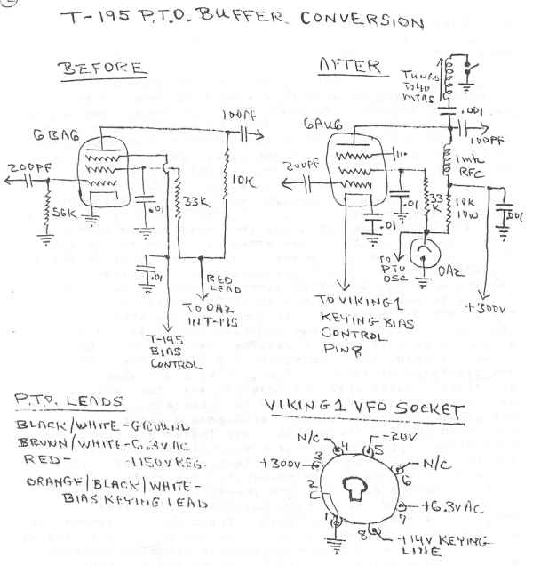
Over a year ago, I purchased a Viking I transmitter and model 122 VFO. I rebuilt the Viking I with helpful hints from Tim, WA1HLR. The model 122 VFO had a nasty habit of jumping frequency in no particular pattern, no matter what changes I made short of a complete rebuild. After much frustration, I bought a T-195 PTO from fair radio sales for ten dollars and change, plus other parts to make up a minimum order. A request on the AM swap net, got me the diagram for the complete T-195 transmitter, plus color coding of the leads and pin connections on the PTO plug, which I cutoff as I did not have the mating socket.
Looking at the diagrams for the T-195 PTO, Viking I and 122 VFO, the first thing I did was to remove the wiring cover on the PTO and connect the filaments in parallel for 6 volt filament feed from pin 7 on the back of the Viking I. The next step was to rewire the PTO buffer to mimic the 122 VFO as follows: first I replaced the 6BA6/5749 PTO buffer tube with a 6AU6, to utilize bias cutoff control from the Viking I. I then ungrounded the PTO buffer cathode and bypassed the PTO buffer cathode with a .01 mfd disc ceramic cap to ground. Next I grounded the PTO buffer suppressor grid to ground, discarded the bypass cap, and lifted the T-195 control wire from the PTO buffer suppressor and connected this wire (orange/black/white) to the PTO buffer cathode for bias control from pin 8 on the back of the Viking I. Then I removed the PTO buffer plate resistor and brought the PTO buffer plate directly out through a I mh RF choke to +300 dc from pin 3 of the Viking I, to get sufficient output from the PTO.
Click here to see the T-195 PTO conversion schematic
I mounted the PTO in an aluminum box, along with a terminal strip and a small shelf, on which I mounted a socket for an 0A2 regulator tube. The PTO B+ (red lead) goes to the 0A2, and a 10,000 ohm 10 watt Globar resistor goes from the 0A2 to +300 dc from pin 3 on the Viking I. The PTO filament wire (brown/white) goes to pin 7 on the Viking I. The PTO ground wire (black/white) goes to pin 1 on the Viking I.
The PTO output is on 160 meters, but it produces sufficient output to operate the Viking I on 80 and 40 meters as well. If the Viking I is to be operated on 20, 15 or 10 meters, then you will have to add a slug coil, blocking cap and switch, to put the PTO output on 40 meters like the 122 VFO.
In conclusion, this PTO is the best investment I ever made. The warm-up drift is between 0.2 and 0.3 kHz, and the warm-up is usually under 10 minutes. The PTO is uncalibrated, but for the price it is a real bargain! It should be noted that the PTO oscillator is on continuously, and the PTO buffer is cutoff on receive. The shielding is adequate so that you do not hear the PTO oscillator on receive.
![]()
The Multi-Elmac PMR-6A
Mike Koscak WA1MTZ
605 Loomis St.
Westfield, Ma. 01085
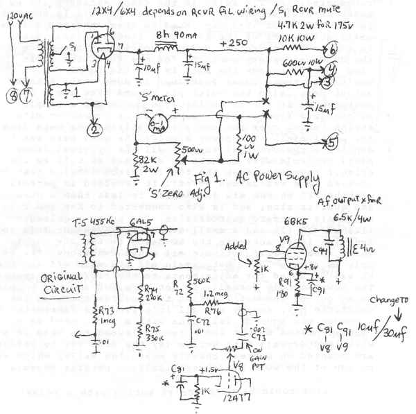
The purpose of this article is to acquaint the reader with this fine rcvr. Some of the desirable features are small size, low power consumption good selectivity, stability. A good mobile rcvr! A later model employed a squelch circuit which is very desirable especially used with a VHF converter. Ten tubes are employed including a V.R., BFO and noise limiter. Frequency coverage is the bottom of the B'cast band to 2010 kc. Continuous, single conversion to 455 kc. IF, then the rest of the bands use dual conversion with a 1600 kc IF. It is this IF that drifts out after long term use, a good modification here would be to use a xtal in place of the tuned coil that is used. The power required is 12v at 1.8A and 250 vdc at 90 ma. Though I currently use a surplus vibrapack, PP-281/GRC, which gives me about 175 vdc., I even let the primary DC supply down to 7.5 volts and the rcvr still worked! Mine was a real basket case when I got it, the clear plastic dial was anything but clear, in fact I wasn't quite sure what it was. The case was very rusty and reeked of mold. The aluminum nameplate on the back was carefully cleaned of corrosion with 000 steel wool and given a quick spray of polyurethane. The cabinet was "wooled" too and sprayed with Rustoleum gray to match. The plastic dial was cleaned with soap & water, but you could not see through it! Very fogged and scratched! Slow drying spray polyurethane was quickly and carefully applied so as not to warp the plastic. The fast drying stuff or lacquer has stronger drying agents that either melt or turn the plastic white. The result was a clear dial plate that could now be seen through. The speaker output is 4 ohms and the audio, I found to be unacceptable as it is very tinny-and sounds like one of those $5 transistor radios. A few simple mods produce pleasing sounding audio. With a gentle rolloff at the hi and low ends. Response was measured with a modulated signal gen. with a H.P. lab quality modulating source at 15 % level and a Heath VTVM using the db scale across the speaker. Overall response is 60-6000 -15 db, 80-5000 -10 db and 140-4000 6db.
Click here to view the PMR-6A mods
Around the 6AL5 tube, the following component changes were made -- first is the original and second is the change. C94, .005/.002 (on the 6BK5 output tube plate, V9* and an addition of a 1K .5w in the scr. pin 8) C72 .01/330 pf C73 .002/.01 R72 560K/70K R76 1.2 meg, removed. That's it. Power plug wiring and AC supply as well as an external 'S' meter is included in Fig. 1. This rcvr is very worth while to acquire! Also a heartfelt thanks to Bob N1DQM for providing me with a copy of the manual which proper alignment would have not been possible, as the coils are on top and bottom of the chassis, are staggered, for the RF, Mixer and Osc.
![]()
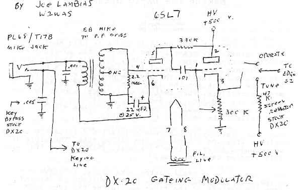
Making the DX-20 Speak
Joseph Lambias
2521 Aster Place N.
Westbury, NY 11590
Converting a DX-20 to phone is hard because the original h.v. trans. leaves little extra power. The stock one ran hot even on standby. This rig used up two replacements over the years. I decided to find a husky new one to fit inside. The new one had two 6.3 v. fil. windings. I took out the 5U4G rect. tube and … [installed] solid state rectifiers. That left an empty octal socket to use for the modulator. I decided a small gating type screen modulator would be best with a Carbon Mike yet the more Yellowy the better (to be heard).
Gating type screen modulation derives the screen voltage from the cathode of the gating tube. Therefore an ungrounded filament line is a must. That's where that extra fil. winding came in handy.
I had a small carbon mike trans. to drive P.P. grids that fit inside nicely. Button voltage is derived from the cathode of the first section of the tube 6SL7 as shown in the diagram (look Ma, no battery). The 300K pot is across the final screen supply and the arm adjusts the voltage output by varying grid bias.
In the tune position as well as normal C.W. operation the original screen resistor is used. In the Operate position the modulation varies the bias on [the] gate-tube and also the Final (6DQ6) screen voltage.
Screen modulated rigs are best tuned up first in Tune position for maximum output (even above rated tube specs). Then switch to Operate position, adjust the 300K pot to about 75 Ma. Plate Current & start talking into mike while monitoring with S.W.R. Bridge on the output. A point can be found from Constant Carrier to Pulsing Carrier Control a la DX-60.
I also have a Heathkit AT-1 but have not tried the gate-mod on it. Incidentally the 6L6 and 6DQ6 base is almost the same except pin 3 on 6L6 is Plate (no cap).
Click here to see schematic of DX-20 modulator
![]()
EXCHANGE
FOR SALE: From estate of Don Scott, WA4UGR. 1988 Mazda Cab Plus LX B2200 truck with 5-speed stick shift. 63,000 miles, has had oil changed every 3,000 miles. All new belts and extra good tires. Equipped with ham radio antennas and wiring, CB radio; topper for camping is permanently attached. Don bought new in 1988. Two-tone blue. Never wrecked, but back bumper is slightly dented. Would like another ham to own it. Asking $4800.
FOR SALE: Hi-power tubes new and used. Also hard to get parts; old tubes rx and tx types. Oil caps, variables and coils. SASE for list. Cash and carry, on ship.
WANTED: Schematics for AN USM/398 scope (70's vintage), TBM-50 and BC-AR-430 transmitters (WW-II).
WANTED: Still looking for old style pushbutton a.c. light switches and cover plates, other old electrical hardware and fixtures.
FOR SALE OR TRADE: SX28, SX25, Ranger I. WANTED: NC100X, HRO pre-war, HRO coils E and/or F, Skyriders, Silvers, Sargents, Bretings, RCA ACR-111.
MAKE A STATEMENT! Be the hit of the hamfest, or your local radio club meeting with this DARING T-shirt that pulls no punches and SAYS IT ALL!! "I HATE SLOPBUCKETS" in bold, black, block letters is emblazoned across the chest. Just below that, in brilliant florescent yellow (with really neat sparks), is "AM Forever." Quality Fruit of the Loom, made in USA. Available in grey, red, blue, and green, in sizes M, L, XL. Just $15 ppd. Make check or MO payable to "Hate Slopbuckets."
WANTED: Modulation Reactor, approx. 40 Hy, 500 mA.
FOR SALE: RCA commercial power transformers, PRI: 190-210-230-250 VAC, SEC: 4500-4600 VAC CT, rated at 1.75 KVA, asking $75 ea. The above transformers are very husky, designed for continuous commercial service and have never been used!
WANTED: HT-5B or HT-5 control unit for the HT-4B transmitter (civilian BC-610). Also want the AT-2 or AT-3 antenna tuners for the HT-4, manuals, schematics and any related info. Lastly, anyone know anything about the Hallicrafters military CY-1218 "Control Radio Set"?
FOR TRADE: Classic radio collection. Trading items include pre-war communications receivers RCA ACR-175, National NC-100X (1936), 1938 NC-101X (early model with eye tube), complete rackmount HRO-M, Hallicrafters silver-dial 1937 SX-16 Super Skyrider and S-19R Sky Buddy; all wave receivers 1933 GE K80 tombstone, 1935 15 tube Lafayette C-53 tabletop; postwar transmitters Heath AT-1/AC-1, Gonset Communicator, Elmac AF-67 with power supply; postwar receivers Knight Span Master and Hallicrafters SX-110. Some rigs are restored and operational, some untouched original, some require "unmodification." Trading any/all for pre-war telegraph keys, including spark straight keys, McElroy keys, early Vibroplex, other unusual make/design bugs. Trade for keys only; cash offers not considered.
W7FG Vintage Manuals - Most manuals in stock.