
Issue #109
Scanned and OCR'ed by Mike Warren, W5MAZ
![]()
Camera-Ready Articles Wanted
Recent mail from readers indicates that some of our newer subscribers are not aware of how The AM Press/Exchange works. Yes, we do take submissions from readers. In fact, we depend on our readers for most of the articles that appear in this publication. We invite articles on any subject that might be of interest to the AM community. This includes technical articles on the design, construction or modification of AM transmitters and receivers, tips on design and construction techniques, news of recent happenings that might interest the AM community, news of any action by the FCC, ARRL or other institution that could have an impact on AM operation, news or stories concerning members of the AM community (including deaths), comments and opinions in response to recent events or articles published in this or other publications, human interest stories, even fiction. If you know of AM equipment up for sale or disposal, please send us the information in the form of an article (with photos if possible) or an ad for the EXCHANGE section. We Invite all articles pertaining to AM, tube or solid state. We believe that amateur AM is a multi-faceted specialty, not narrowly limited to tube technology, vintage equipment and nostalgia.
Please note that we prefer that submissions be CAMERA READY if possible. This means -typing it on a typewriter or computer/word processor in such a manner that it can be photocopied directly for publication, without having to be re—typed. This explains why many of our articles in the same issue are obviously typed on different machines. If you are unable to submit the article camera—ready, we will not refuse it, but there may be a considerable delay before it appears in publication.
The reason for the camera-ready policy is that this publication is a one—person enterprise and operates on a "shoestring" time—wise as well as money—wise. The editor/publisher simply does not have time to retype articles in addition to all the other steps necessary to get an issue in print, especially since the workload from my regular full—time employment has drastically increased in the last three years.
The purpose of this publication is to provide the AM community with access to vital information, which may not be available from other sources. In addition, our mailing list maintains an up-to-date roster of active AM’ers to be contacted immediately in case of urgent need, as for example the release of an FCC Rulemaking Docket or Petition that could adversely affect our AM privileges. In the meantime, we try to provide our readers with articles which are informative as well as entertaining.
Please help us to achieve those goals by keeping the articles coming!
—K4KYV (Editor and Publisher)
![]()
AM International
AM International Election of Officers for 1994
Nominations for AMI officers were concluded in November. Only one nomination was received for each office with the exception of the Great Lakes Regional Director which is currently open. Nominees for each office are thereby declared to be the new holders of these offices for the 1994 term.
President Dale Gagnon, KW1I
Treasurer Warren Ziegler, NY2H
Directors:
Northeast Steve Ickes, WB3HUZ
Southeast Andy Howard, WA4KCY
Great Lakes Open
North Central Skip Green, K7YOO
South Central John Firey, WB5HRI
Rocky Mountain Bill Kleronomos, KD0HG
Northwest Pat Person, K7YIR
Southwest Bill Neeley, K7INKAn interim director for the Great Lakes Region will be appointed.
Lack of competition for AMI offices is not necessarily a bad sign this early in our organizational history. AMI has demonstrated a commitment to democratic principles in the selection of its leadership. This will ultimately insure AMI’s responsiveness to its members and its long term viability.
![]()
Ten-Tec Adds AM
Ten-Tec has reversed its anti-AM company policy and added AM transmit capability to the Paragon II transceiver. Ten-Tec Marketing’s Tom Salvetti states that the company is now striving to be more customer driven and that denying the AM transmit mode was both controversial and wrong. He also indicated that pressure from the AM community did a great deal to change the company’s view. AMers looking for a ‘modern’ transceiver may wish to consider the Paragon II before making a decision. I suggest sending a note to Ten-Tec, thanking them for supporting AM (1185 Dolly Parton Parkway, Sevierville, TN 37862).
Jay Mathisrud, WB0L
![]()
WA3VJB August 26, 1993
Annapolis RadioMr. George A. Flanagan
Amateur Operator W2KRMDear Mr. Flanagan:
I am mailng this to you via Mr. Wiseman at Electric Radio hoping to continue a positive dialogue on contemporary AM issues.
A lot of people in the AM Community would take issue with your claim that AM takes up two seats on a crowded bus." Many of us think of good audio as offering a first-class seat instead of one in coach, at a time both are available on the bands.
A long time ago, AM moved from the mainstream and into a specialty status that effectively settled the merits of the bandwidth argument you still hang on to. We find no such controversy over the merits of any other specialties in the hobby nor the spectrum they happen to take up.
Contesting, DX-ing, Scripture nets and others are all afforded a rightful place on the bands. Those SSB stations, however, have no greater claim on spectrum than those of us on AM - - their communications have no special importance over ours or anyone else (emergencies excepted).
Your sentiments are very similar to the questionable attitudes held by anti—AM folks, and I had to blink and look twice at your letter to see whether you had actually identified yourself as among that crowd.
There is a rising number of people who think it’s downright selfish of critics who try to use the bandwidth argument to stake a claim on spectrum. Would you also prefer that all Amateurs face an "essential communications" standard? That’s the only way to achieve the maximum spectrum efficiency you seem to support.
All too many narrow—band audio advocates are also narrow—minded. And the type of judgments you proclaim in your letter simply add to the evidence you may be included. Check yourself - - would you support and comply with rules that allow operation based on content? And what would you do if you found yourself excluded because your desires are not "acceptable?"
It’s not a fantasy that some of us adopt a "broadcast quality" mentality. It represents, in many cases, the kind of respect, good-natured fun, and high technical standards that helped shape the Golden Age of Radio. Too bad you seem to be calling for protests against someone’s responsible use of spectrum.
We are already providing what many present—day Amateurs long for -- your wish for-"a taste of vintage operating practice and courtesy to complement the sound..." as you put it. But there’s a difference between hearing such stations and listening, and I’m not sure you know which is which.
Paul S. Courson Box 73 W Friendship. MD 21794 AM Radio Network
![]()
Restoring a Heath AT-1
by Marty Drift
This AT-1 was ready for the junk heap. But, a little patience and inspiration gave it new life. This rig was bought "as-is" for only $1 at a Ham Fest.
The AT-1 was the first ham transmitter in kit form to hit the market. It was introduced about the mid 1950’s and sold for $29.50. Many of these transmitters were sold and it led Heathkit to success in ham radio.
This AT-l is the only one I’ve ever seen at any Ham Fest. I am somewhat of a collector of fine Heath gear and I just could not let this one go. I felt it would be a challenge to bring it back to life. The rig was torn down to kit form. All of the parts: screws, sockets, transformers, coils, etc., were taken off the chassis. It was literally torn down to the bare bones. The chassis was replaced with a chassis from Mike K5FZ. It was the only part that was replaced from another AT-1. All tube sockets were unsoldered. The transformer was broken down and the outside was repainted. New capacitors, resistors and wires were installed and the hardware was replaced. The Heath manual was followed to the last detail. Heath, even back then, did an excellent job of step-by-step instruction. Once complete, the rig was turned on. It worked immediately and is still alive today!
Now I am restoring a VFO for the AT-1; The VF-1. Soon the AT-l will no longer be rock bound.
It seems that the love affair such as the one that I have with Heath is spreading and more people are involved with restoring old Heath equipment. I receive at least ten telephone calls a month concerning the sale or trade of Heath parts that I may have. Heath equipment is easy to fix, maintain and use. More importantly, by restoring such equipment, we are saving the Heath heritage.
So the next time you see an old rig like the one in the photos, remember this little story. Also, after you have torn down a piece of Heath equipment to piece parts and have restored it by the book, you can truthfully say you have built a Heath kit.
![]()
Things I Learned While Reading....
RADIO, January, 1936
The Chicago Daily News once employed a special messenger to take messages to be relayed by Chicago hams. About the same time, the St. Paul Dispatch-Pioneer printed and distributed special radiogram blanks to help local hams round up traffic.
…
Doctors used to call alternating current "Faradic" current.
…
Alfred H. Grebe was a remarkable radio pioneer. He was a commercial CW operator by age 15 and a radio manufacturer by age 20. His firm made precision spark gap transmitters and regenerative receivers. Everything in the Grebe "Synchrophase" receivers was hand made from the raw materials in a single building. That building was built on the site of Grebe’s father’s home. It had to be constructed around a linden tree that his father had planted and Al refused to remove.
…
Grebe built the first WABC station (later a CBS flagship, oddly enough) and pioneered many radio design improvements including tone control, high-fidelity audio and one-control tuning. Grebe receivers had gain and selectivity that was said to be outstanding and unique in their time.
…
In 1936, Great Britain licensed a number of stations for dummy antenna operation only.
…
(From the review of the RCA AR-60 receiver)"...We found that RCA has been very shy in regard to a definite sensitivity statement for the somewhat amusing reason that the truth would look bad alongside of some--shall we say "optimistic statements?" [of competitors]...Mr. Glenn Browning has in effect agreed with this same feeling by arguing that unless someone knows something about the NOISE output it is rather useless to talk about sensitivity...Both the RCA objection and the Browning-Tobe objection center around the fact that there is such a thing as a receiver that makes so much noise of its own that it can turn out nearly standard output WITH NO
INPUT AT ALL!"
--Don Merz
![]()
MEET THE AM’ers
Click to see a Photo of W3ONE and Shack
Tom Long, W3ONE, is shown at his AM station in Rockville, MD. The transmitter is a DX-100 with an NC-303 receiver. Also pictured is a Gonset G-76 with power supply and a TS-140 with power supply.
![]()
Frederick, MD Hamfest
Tom sends the following report on the Frederick, MD hamfest he attended in July. It was well attended, with about 1000 amateurs looking over (mostly commercial) stuff in two permanent buildings, one enormous tent, and several acres of tailgaters.
A sampling of vintage items being offered: National NC-125 $60, Hammarlund HQ-129X $95, Hallicrafters SX-101 $150, SX-28 $100, Johnson Viking Navigator $175, KW matchbox $275, Heath IT-17 tubechecker $20, SB200 $325, Collins 51S1 (excellent) $900, 51J4 (fair) $400, Gonset Communicator II $20. This list represents about 25% of all the vintage items displayed. Most gear was in good to excellent condition.
The food wasn’t bad; breakfast consisted of fresh scrambled eggs and real country sausage (for those not on low-fat diets), but the lunch menu was the usual grease dogs and mystery burgers. But most of us do not attend hamfests with the food in mind, do we? Best of all, the ice water was free!
![]()
You Can Build A S.B.E.
by WA1HLR
What is a SBE you ask? .Most people think S.B.E. stands for Sideband Engineering Co. In the book of Henry Nyellar it stands for Slop Bucket Eliminator. How does a SBE work? What are it’s characteristics? But most of all, what is it? The SBE mode has been around since the dawning of AM radiotelephony. It is a by product of modulating an oscillator, In other words: FM. In the early days of radio, the governmental radio regulatory, probably the FRC, The Farce, a predecessor to the FCC, The FeeCCee, made the SBE mode illegal and relegated SBE operation to the 2½ meter band and above. A lot of experimenters were using tuned line oscillators Etc. with weird looking tubes like the HY 75. The No FM with AM rule was on the books for so many years, That when the FeeCCee re wrote or shall we say put into plain language the rules and regs governing amateur radio they left out the clause "Thou Shalt Not Amplitude and Frequency Modulate simultaneously" I have searched a recent copy of the latest FeeCCee rulebook and I have yet to see anything blocking the path to a legitimate use of the SBE mode. Why operate the SBE mode you ask? Why put out a signal that is less than perfect. How many times have you been operating on a clear frequency and had some sideband operator fire up almost on YOUR frequency, make some mention of the weak AMer in there and " Oh I can notch his carrier out". The only way it seems they become painfully aware of your presence is when your carrier drifts into his pass band or you happen to have the audio capability to modulate 200% positive and broadcast audio processing with premphasis. The guy with the stock DX-l00 or Valliant just does not cut the mustard. Time to press some SBE technology into service. How does one get with the program here? Some of us are operating S B E type transmitters without even knowing it. Take for example the recent resurgence of military radio equipment. Take the BC 375/191 with it’s 211-211 MOPA circuit or these little GRC 9 backpack rig or the evermore popular ARC 5 command set transmitters. They all have a certain SBE factor to them .If you live in the northeastern part of the US tune into the military Radio Net Saturday Mornings at 5 Am EST and you will hear a plethora of S B E type signals. The problem is that they are all low power and rather low modulation capability. Doing some audio improvements and use of a linear amplifier can do some serious damage to some slopbucketeer who decides to plonk on down or your frequency. Some amateur transmitters would inadvertently SBE like the Harvey Wells T-90 on 80 Meters and the Heath DX-40 and DX-60 on 40 meters along with some Johnson Rangers and Valliants. The problems all occur when the VFO frequency runs straight through. Other S B E problems occur when power supply regulation is poor. All of the above listed methods are referred to as Low Level type S B E. The type of S B E rig to be discussed here is that of the High level S B E. I have always had an interest in very simple transmitters. My first real transmitter was a Knight kit broadcaster kit. This transmitter had a 50C5 oscillator final and another 50C5 heising modulator with a 12AX7 microphonium preamp . A real transmitter not just another screen modulated phonograph oscillator. I received a kit for Christmas. It was not long before I improved the circuit. Here is a version of the circuit similar to the one in the DFO (driftable frequency Oscillator)
Click for a diagram of the circuit
The simple circuit that was just shown is a good beginners SBE final . You can steal modulated B+ from an existing transmitter such as a Ranger or DX-l00 or any other power supply/modulator source. The screen voltage should be adjustable preferably from a fairly stable source but what the hell good engineering practice is out the window here. By playinq around with the antenna coupling (S B E Loading) and screen voltage one can keep the SBE factor within limits of the bandwidth of the other guys receiver. Do not expect typical class C efficiency out of this unit. You should get enough power to drive the typical slop bucket linear amplifier to a reasonable outpoot. A simpler type of S B E utilizes a triode. For maximum stability a low Mu type is preferable. There are many types of oscillator circuits applicable to S B E operation. In the circuit shown here a tetrode is used. This worked out well for broadcast band operation. The circuit was developed many years ago with the advent of the DFO (driftable frequency oscillator), a piece of equipment that had an honored spot in my early hamshack. The DFO used a single end 6L6 modulator and back to back audio transformers to modulate the 6BG6G final. The DFO was around for many years until recently. The DFO was a bandswitched type S B E that covered 500Khz - 5.0mhz. Recently a 75TH bandswitched S B E was constructed covering l60 - 75 -- and 40 meters. It is not advisable to use SBE technology much higher than 40 meters. It is difficult to keep the SBE factor and stability within reasonable limits. In operating a S B E one should monitor their own transmissions with a receiver with the BFO on to check for drift. If the drift is 1Khz or less during the course of a transmission that is considered good. It will be noticed that when the wind blows and the antenna floats up and down so does the frequency. This is known as the incidental swish factor. This is most helpful in ridding the frequency of unwanted slopbucket stations. The FeeCCee cannot pin a malicious interference rap on you because you are not doing the swishing Mother Nature is doing it for you. In the course of looking for parts to build a big AM rig and foraging around for items at the local ham fest, one usually will run across some small or medium sized transmitting type triode. Larger tubes like the 304 TL and 833A make great high power S B F finals. A 304TL SBE is planned here at WA1HLR radio . A smaller model SBE has already been constructed and tested . A 75TH was used. Test results with 1250 Volts on plate produced very satisfactory results. Photos and operational test results with full details shall be presented in a future SBE article.
We have only scratched the surface in practical application of SBE technology. What does the future hold? Who knows. Different methods of obtaining stability may be added . The use of the Electron Coupled Oscillator circut using a tetrode like a 4-400 or a pentode like an 803 may usher in a new era of stability to SBE technology make operation on bands higher in frequency than 7Mhz practical. So good luck my fellow homebrewing AMers and happy S B E ing to you!
The Timtron, WA1HLR -
![]()
YOU COULD BE USING A SIGNIFICANT READABILITY IMPROVEMENT
ON YOUR A M RIG BY SIMPLE PREEMPHASIS AND DEEMPHASIS
By George A. H. Bonadio, W2WLR, 373 East Avenue, Watertown NY 13601-3829
Part VIII
FILTER WHAT FREQUENCIES?
We need the two filters to cut back treble just above 3,200 Hz, briefly, at a spectacular rate averaging -225 dB/O (per Octave). This is better than what SSB is able to do with its 3rd order harmonics. Our resultant, then, should be about 40 dB better than we have been doing, which has been poor, sometimes very poor. Two of our signals, with roughly equal carriers, at 8,000 Hz apart, each with this high definition audio, should be not noticeable on the adjacent channel. We need to be clean, instead of splattering all over each other. (In the civilized city we do not throw our trash over the fence, because everyone is vulnerable, and life would be terrible that way.)
Earlier today I removed my filters and tested on unused bands. I held the modulation to a limit of 95% and drove the compressor hard with hisses. I have my receiver’s antenna trimmer with a bent plate so that when it is turned over, it shorts, so my front end is not overloaded. I could hear trash all the way out to ± 18 kHz. Then I raised the compressor output to 105% modulation and followed overmodulation trash out to almost ± 50 kHz. On frequency my carrier was S9 + 64 dB. I followed trash out past -100 dB, about a billion-to-one down, in power. Automatic overmodulation prevention, by compression, is an important function of this system.
What surprised me was that, with no modulation, and without any filters, I could hear a regular old transistor preamplifier hiss noise out to about ± 12 kHz, which I had not heard before. I replaced one (almost optimum) filter and can see, on my spectrum analyzer, full modulation sidebands at 3,200 Hz, and 4,000 Hz hash at about -40 dB. Nothing shows above 5,000 Hz. With both filters in, nothing shows above 4,000 Hz, and the hiss is gone, too.
BANDWIDTH TESTING CARE
When we monitor our own signals, in our own receivers, connected by coax to our own transmitters, we have special problems. Besides the bent plate technique, just above, I find a need to filter signals off the outside of lines entering the receiver for any reason.
I find the NOISE FILTERS 3224-FL, Type 1, $0.75 (pair) from Marlin P. Jones, 1 (407) 848-8236, so effective that I have used almost 50 pairs in choking radio signals off the outside of numerous wires to chassis.
Once you have cured a problem with them, I don’t expect that you will want to run out of a ready supply of them. They are two each one inch pieces which are center grooved to fit around wires up to RG 58, even, with finer wires, with multiple turns passing through the opened hole.
These ferrite clamp-overs have taken me out of telephone lines, FM receivers, audio amplifiers, TV, and on my Collins 75A2 receiver. I found that the hum in my monitoring of my own clean-of-hum rig was RF coming into the receiver on the outside of the AC line. The rectifiers did the mixing to produce the hum.
When I cranked down from 75 M to 15 M I had audio feedback, until my audio gain was too low to be useful. Two pairs of these clamp-around-ferrite-filters on my mike line, inside the chassis, let me turn the gain way up, past needs, without feedback. Recall that our voice gain, in the treble, is up as high as + 24 dB, so more than conventional filtering care is required.
NO ACTIVE FILTERS
While active filters have their places, they are not desirable here. Some types radiate noises, in the Ham Bands, when we are frying to hear "the weak ones." Some are expensive. The passive filters are good for us. Yes, they take up some room, and have some weight, but with close tolerances of values and with modem design, they do superior cut offs to what was accepted a few years ago.
Ed, W3NQN, has written numerous stories on the "elliptical" low pass filters. For example, Simplified elliptic lowpass fitter construction using surplus 88-mH inductors," RADIO COMMUNICATION, April 1983, published by the Radio Society of Great Briton. Also see "Elliptic lowpass audio filter design," HAM RADIO MAGAZINE, February 1984. Recently he helped me to make a great improvement in my roll-off rate. His design gives me about three times the minimum cut back, in his 3 stages, as I was getting in my 5 stages. We get back to Ed’s design later.
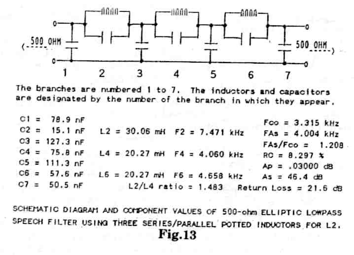
The first construction we should consider doing is building our low pass filters from Ed’s superior designs. For our PRE-box we will filter audio in a circuit with no DC, and with only about a volt of signal. We can use quality C’s here, but at low voltage and small size, for low cost. See Figure 13.
There are three resonant stages or sections made up with standard surplus 88/22-mH toroidal inductors available from Ed. What is unique about this ELPF design is that it has an impedance level of 500 ohm, a measured 3-dB cutoff frequency of about 3.4kHz, and acceptance minimum stophand attenuation of about -46 dB. Also, it can be realized with a combination of only five of the surplus inductors. The capacitor values may be obtained by paralleling two "even numbered capacitors" to get the design values within ± 1%, and at ±3% for odd # C’s. Then the measured return loss and attenuation responses will match the design responses. What this means is that we are not going to improve on Ed’s design by tinkering with any of the values.
ED’S FILTER LAYOUT BOARD
In Figure 13 we number associated L’s and C’s for their positions among 7 numbered C’s, so there are no L’s of # 1, 3 or 5, but there are #2, 4 & 6. L2 is about l50% of L4 or L6. In the 500 ohm version L4 & L6 are near 22 mH each.
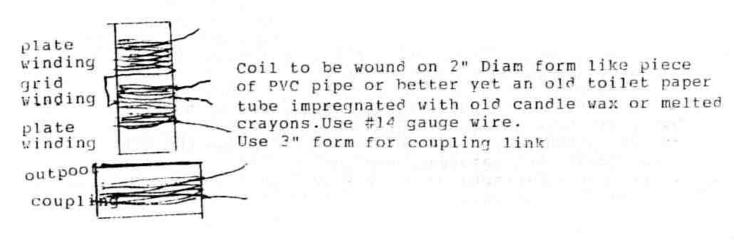
All the C values are obtained by paralleling two 10 % (or better 5%, 2% or even 1%) C’s "selected" so that the pair gives a measured value that is within ± 1 % of the design value. To do this conveniently, a capacity (digital) meter is required that is accurate to within 0.5 %. (I have been using Mouser (1-800-346-6873) 100 V @ 1% Mylar for low voltage service.) Ed recommends the Panasonic 100-volt miniaturized metallized polyester film capacitors, type ECQ-E(F), distributed by DIGI-KEY CORP. 1-800-344-4539, for building up the PRE-box filter.
It is easiest mounted on a double layer of corrugated cardboard. C pigtails are sewed into the upper layer. String turns are used to anchor the toroid "doughnuts" to the upper layer. Ed reminds us to use common ground of # 16, or heavier, copper "buss bar," to stop "mutual coupling" from thin wire, which would spoil our curves. It is sewed along a long side. Be generous with solder. Remember, solder has about 13 times the resistance of copper. Use plenty. A bottom cardboard then covers the bottom for insulation. OK, ok, so you can do better with a board from Radio Shack, with standoff feet bolts, or your own way.
PROOF OF PERFORMANCE
This design is for a load Z of 500 ohm, so we need a test load of two 1,000 resisters in parallel (= 500 ohm) across the output terminals, where we also connect our dB meter, VOM, or analog ACV meter. We inject a signal from a generator having a well-defined 500 ohm source Z. Ed says that if your signal generator has a source Z other than 500 ohm (600 and 1,000 are common values) then a minimum loss R matching pad must be connected between the generator and the input of the filter. It is important that the filter "sees" a steady 500 ± 5% at both "in" and "out" if reliable measurement results are to be obtained. (For information on resistive attenuator design, see Ed’s "Simplified Attenuation and Impedance Transformer Design," ITEM 1992, published by R&B Enterprises, Conshohocken, PA. A copy of this 8-page article is available from Ed for $5 postpaid.)
When we inject a signal of about 10 volts into the filter we should see very little difference in output from 100 Hz to 3,000 Hz. Then, above 3,000 Hz we should see a rapid drop in output, by about 45 dB (= 31,620 : 1 in wattage, 171 : 1 in voltage) at 4,000 Hz and beyond, with no loss as little as 45 dB at any higher frequency. Then remove all the Z load test resistors, as they were for test use only.
C VOLTAGE TEST VALUES
Each construction needs a (smoke) test. Lay this unit away where you will be ready to use it in your PRE-box, later. Meanwhile, you could use a similar LPF in your audio driver to final grids path. However, if you make a filter for your 500 ohm higher level audio line, then you need higher values of voltage rating for all these C’s. Do not run over 20 mA of DC through any toroids. For up to 100 W, maximum, of stray peak audio drive, use 630 V values. More W will saturate the cores producing trash, instead.
For Ed’s design ELPF, to protect the resonating C’s # 2, 4, and 6, from excessive voltages, above 20 Watts, connect a one or more watt R across each, with a value of about 47 k ohm up to 100 k ohm maximum.
Most such lines carry audio of about 20 W, but they have capabilities of a switching surge to drive to full output, square waves and all. Thus, a Ranger used about 20 W to drive its KW amplifier. However, its audio is from a modulator of an RF of 65 W peak input. Thus, it can hit output peaks, from switching, distortion included, of well over 65 W., close to 100 W. These figures are for only the 500 ohm filters.
HIGHER THAN 500 ohm FILTERS
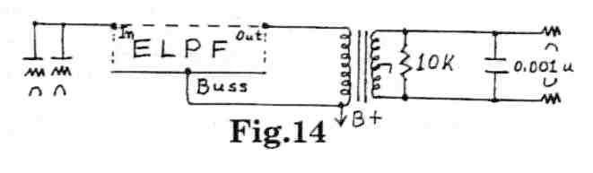
We have to have a second filter in the rig, somewhere near the output. This is both to sharpen the cutoff and to catch the accumulated audio harmonics developed in route. The 2nd filters, in the 500 ohm lines, above, accomplish that. We are left with needing a filter to go into the circuit between the audio "driver" stage plate (and any screen) and the first audio transformer input. This is for use in the many rigs which do not have any 500 ohm line for audio, mostly inputs under 250 watts.
We will insert this, as in a Ranger, as shown, in Figure 14. Notice the added 10,000 ohm R across the C, on the secondary, which C has been changed from an old 0.005 to a new 0.001.
If we do not get a perfect match in the filter design Z to the actual Z there, we will lose some of our filtering efficiency. However, we have ample safety margin for our design by going to a style very similar to that in Figure 13.
It is bigger due to needing much more L values. We are using a design averaging near 2,500 ohm. It uses about 5 X the L and 1/5 the C, at each place, in the same circuit.
Our audio W, here, is probably less than 5 W, but we are in high voltages, typically 300 V to 400 V. This level, plus heat in the chassis, plus wide voltage swings on the higher Z, requires, for safety, at least 600 V values of
C. Ceramic C’s are tempting in their marked 1,000 V values. Actually ceramic operating Q’s are poor, their accuracy is very poor, their drift in value from heat is usually bad, but I don’t expect that to harm use by more than a few dB. I prefer the Film C’s of 630 V, in the small tolerances, and measured on my capacitance meter.
We are using a design for a Ranger source Z of 3055 and a load Z of 2500 ohm. The filter type is designated as a sixth-order elliptic having a 10 % reflection coefficient, a return loss of 20 dB, a minimum stopband attenuation of 43.6 dB and a ripple cutoff frequency of 3,000 Hz. The L2, L4 and L6 inductors of 176, 153 and 135 mH are realized with a single stack of the 88-mH surplus inductors. Two 88’s are put in series for L2. One of the inductors is removed from the stack and turns are removed to give 65 mH. (Ed supplies the info with the particular inductors he supplies.)
The inductor is then returned to the stack and wired in series with an 88 to give 153 mH. L6 is obtained by wiring the fifth 88-mH in the stack in series with an external 47-mH inductor stuck on the end of the stack to give 135 mH. C7 is not required in this design because of the unequal termination Z’s. The C’s of Cl to C6 range from a low of 5.08 nF to 23.4 nF (23,400pF or 0.0234 uF). C’s of less than 10 nF are obtained by connecting C’s in series instead of parallel.
FREE TOROIDS & DATA FROM W3NQN
Ed Wetherhold, W3NQN, has made arrangements with the C&P Telephone Co. of Maryland, for saving their salvage toroids, as they change circuits. (TOROIDS ARE GETTING SCARCE ! CAN YOU GET YOUR TELEPHONE CO. TO HELP ?) The Co. supplies them free to Ed, provided that they go to actual amateur use. Then, Ed may distribute them, at his overhead cost, provided that the amateur specifies for what use they are.
For the 500 ohm filters, "Style #SPL2#l," Ed will provide five potted inductors with a diagram and the exact C values required, based upon the measured inductors he sends to you. Send a check for $5.50 payable to ED WETHERHOLD; 1426 CATLYN PLACE; ANNAPOLIS MD 21401-4208 to cover his costs of packing and shipping the free toroids.
If you absolutely insist on Ed doing all the work, including neatly building them, on a board with terminals, with 4 corner standup bolts, nuts, washers, and testing them out, Ed will do yours personally for $100, complete, delivered, the best. It is FILTER 3A. These curves are slightly better, starting like SPL2#1 at 3,300 Hz, but making its first notch at a desirable 200 Hz lower in the spectrum and 3 dB deeper, and this size is somewhat smaller, only 2" X 5" X 2," and lighter. My 3A weighs 12 ounces.
To Be Continued.
![]()
EXCHANGE
(Note that all names have been omitted since these are past issues)
FOR SALE: 4D32’s new in original box $75 each
FOR SALE: National neutralizing condensers disc type, 2 3/4" diam. $10 pair. Beams Hygain 103BA 3 element 10 mtr little use $70. 153BA 3 element 15 mtr never assembled $90, Octal tubes for HQ-129X, BC-312, BC-348, ART-13 and others $1.50, 837 $5, 811 $10, 1625 $2, 807 $5, UV-201-A, one w/brass-ceramic base, UX-201A, 250, inquire.
WANTED: Original meter and modulation transformer for Johnson Ranger I, QST magazines 1941-44 inclusive, 1950’s vintage mobile ham receiver for daily commuting, preference for Gonset G66, KE93, Multi-Elmac PMR12A.
FOR SALE or TRADE: Large modulation transformers. WANT broadcast transmitter with 833-A’s.
WANTED: Power transformer for National NC-100A or l01XA receiver.
WAITED: Manual for Kaar Marlin Marine transceiver mod # 12TR229. I want to put it on 160. Also, S meter for HQ140X
WANTED: Knight T-400 xmtr, Heath AK-5 spkr for Mohawk, Heath XC-6 converter, VX-1 vox,
TRADES: Meissner 150B (1942) 150 watt AM/CW w/Signal Shifter exciter, WWII Hallicrafters VHF sets (S36, S36A, R-44/ARR-5), more (2-stamp LSASE for list). WANTED: RCA ACT-40, ACT-150 Transmitters and any of the pre-war ACR or AR receivers. National FB-7, AGS, AGSX. Navy TBX, TBY, MAB, PRC-25, PRC-90, GRR-5, PRC-10A etc.
WANTED: National FB-7 receiver, National transmitting condensers, coils and tube sockets, dials and FRC. Also looking for Thordarson CHT 300 w. multi-match modulation transformer. Could trade my SW-3 with doghouse power supply
FOR SALE: Manuals, excellent copies, vintage gear, low profit! SASE for large, descriptive list 700+. List of rigs for sale, large variety, SASE appreciated.
WANTED: Schematics/plug-ins rcvr., R-5007A/FRR-502. Schematic, Scope, AM— USM398. 6 mtr band openings: monitor 50.5 mc. 1st AM repeater in CT (in N.E.) 50.4 input open to all.
WANTED: Tubes 26A6, 2606, 6AJ5.
WANTED: Quote on KWM1 KWM2 or KWM2A, dummy load. SELL type 813 tubes $15 plus UPS or parcel post