
Issue #108
Scanned and OCR'ed by Mike Warren, W5MAZ
![]()
AM Power Not Cut In Half, After All?
Conventional wisdom leads many amateurs to believe that the FCC cut the power limit for AM to one-half the historic level when the new power rules went into effect. As we shall explain, this is not necessarily true. The historic power limit allowed 1000 watts DC input to the final, regardless of the mode. The present rules make no reference whatever to input power to the final. The historic power rules required the amateur to have accurate measuring instruments whenever the input power exceeded 900 watts. Under the new rules, the amateur is required to "comply" with the output power limit, but there is no longer any legal requirement to maintain instruments capable of accurately measuring transmitter power.
The FCC deleted the requirement for power measurement capability because they could not counter the argument that with many amateur installations, it is extremely difficult to accurately measure instantaneous peak RF power output. For example, most commercially available RF wattmeters are unusable with a transmitter in which the RF is coupled from the final amplifier tank circuit directly to an open—wire tuned feeder system, with no intervening 50-ohm coax link. According to the FCC, amateurs may use "methods other than accurate measurement" to determine output power. In the broadcast service, this is called "indirect" power measurement, that is, the output power is estimated, based on other measurements that can be readily made with available instruments.
The alleged 50 percent AM power reduction is based on the assumption that the efficiency of a plate modulated class-C final is exactly 75 percent. According to the tube manuals, that is roughly the plate efficiency to be expected from most transmitting tubes operating under ideal conditions. It does not account for losses that normally exist in the plate tank, coupling circuits and other components associated with the RF power amplifier and antenna tuner. Because of the difficulty of accurately measuring the power fed to the antenna, amateurs tend to be overly optimistic in their estimate of how much power their transmitters put out. In most cases, the actual overall transmitter efficiency is substantially less than the theoretical 75 percent based on the rated plate efficiency of the tubes in the RF final. Nearly twenty years ago, when virtually all amateur transmitters were still using vacuum tubes, the FCC estimated the maximum efficiency of an amateur transmitter to be on the order of 50 percent.
The original proposal to change the amateur power limit to PEP output dates back to the "Restructuring Plan" proposed in Docket 20282, released December 16, 1974. Although this proposal was never adopted into the rules, the FCC remained obsessed with peak envelope power, and once again proposed a PEP power standard in the infamous "Plain Language proposal, which, like the restructuring proposal, was eventually scrapped. But they had apparently made up their minds on the power issue from the beginning, and finally the PEP power limit was adopted in a separate rulemaking proceeding of its own (Docket 82-624). The AM power reduction went into effect despite overwhelming opposition from the amateur community as expressed in the unanticipated large volume of comments submitted.
Quoting from paragraph 15 (the original PEP proposal) in Restructuring Docket 20282, the FCC stated:
"In proposing maximum transmitter power levels, we have taken into consideration a number of factors. Amateur transmitters have not been a significant source of interference to other services, and where there has been a problem, amateurs have been very cooperative. Also, amateurs, by and large, do use the minimum transmitter power necessary to conduct their communications. Therefore, there should be no real problem if the limits were increased in some instances. We would like to improve the technique specified in the Rules for determining power. Modern communications requires better methods for determining transmitter power than the 'plate voltage times current' method. We are proposing to specify the maximum transmitter output in terms of peak envelope (PEP), except at the beginner level where the emissions authorized do permit a fairly accurate measurement to be made of the input power using the method now specified. Under the current rules and practices, THE MAXIMUM OUTPUT POWER THAT COULD BE DEVELOPED WOULD BE ON THE ORDER OF 2000 WATTS (100% MODULATED, FULL CARRIER, DOUBLE SIDEBAND A3) (emphasis ours). Specifying this level as advanced amateur practice ... is the method used to establish these proposals...."
(QST, February, 1975, p.16l-l62)
Under Docket 20282, the power limit would have been changed to 2000 watts PEP output for Extra and Advanced, and 500 watts for Generals. According to the FCC, this figure would have maintained historic AM power levels for Advanced Class and Extra. When the FCC finally adopted their long sought-after PEP power rule, they settled on 1500 watts instead of the originally proposed 2000. In their infinite wisdom, the FCC originally estimated that 2000 watts PEP output represented the maximum possible equivalent to the old 1 kw. DC input power limit.
THEREFORE, THE 1500 WATT LIMIT WOULD REPRESENT A 25 PERCENT DECREASE IN MAXIMUM LEGAL AM POWER, not the often quoted figure of 50 percent. Based on the FCC's own figures and suggested methods for estimating output power, as documented in QST, THE LEGAL LIMIT FOR AM UNDER THE REVISED POWER RULE WOULD APPEAR TO BE APPROXIMATELY 750 WATTS DC INPUT TO THE FINAL, unless the required instruments are available to be inserted between the transmitter and antenna feed point to accurately measure the peak power output.
To summarize, if you are concerned that your station may not be in compliance with the new power rules, and your transmitter works into a nonreactive load of known impedance such as a 50-ohm coaxial line with 1:1 SWR, use a recently-calibrated commercial grade wattmeter, if available, to directly measure power output. If you do not have such an instrument, or if you use a non-coax feed system such as open wire tuned feeders or a single-wire feed system, connected directly the transmitter output terminals, operate your transmitter up to a maximum of 750 watts DC input to the final when high level plate modulation is used.
![]()
More Radiolocation Stations Clutter 160
During the summer static season, many of us do not even listen on 160, but anticipate returning to this band when things begin to get quieter. If you have been monitoring the band this summer, you may have noted that more radiolocation beacons have appeared on the 1900-2000 kHz portion of the band where amateur operation is allocated as a secondary user of this spectrum. During the past 160 M. season, four strong signals were noted, but over the summer, the number has doubled. Radiolocation beacons now appear at 1912, 1932, 1953, 1956, 1960, 1964, 1972 and 1999 kHz. The signals consist of a carrier, modulated at intervals with a frequency shift keyed string of digital data. They somewhat resemble the sound of an amateur station running packet. In between the data bursts, the carrier remains full strength, unmodulated. In addition, the chirping beacons that sound like crickets are still heard between 1915 and 1930 khz, often competing with the data beacon on 1912.
This should be an adequate reminder to the AM community that we must continue to maintain our presence in the vicinity of 1885 kHz, despite the heavy SSB QRM we frequently encounter there. If the radiolocation beacons keep growing in number, it is conceivable that amateur operation above 1900 kHz will eventually become very restricted, and amateurs may even be driven completely off the top portion of the band. If we are eventually forced to confine our operation below 1900, it will be much easier maintain an existing AM window than to re-establish one previously abandoned to the SSB operators who insist on operating in that part of the band.
A ray of hope for this band is that 160 M. radiolocation beacons will be rendered obsolete by the continuing development of cheaper and more reliable satellite location technology. Handheld location receivers are already available to the general public for about $1000 each, and summertime static is negligible in the microwave region of the spectrum.
![]()
Identifying A Modulation Transformer
Dear AX Press/Exchange:
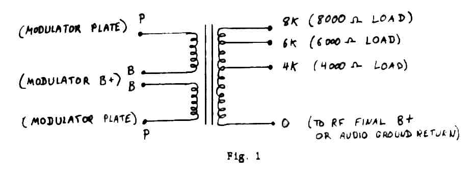
Please, can you help me with some information. I picked up a large modulation transformer, a Thordarson Model 8225. I have a very nice Thordarson catalogue from 1949. It lists many transformers, but the model numbers are like 21M65, etc. This transformer is 8" H X 7 3/4"W X 7" D, blue-grey, and weighs about 40 lbs. It has 8 ceramic insulators marked P,B,B,P and 0, 4K, 6K and 8K. Do you have, or can you locate any further info on this transformer?
Reader From Chicago
Dear Reader:
We have several Thordarson books, dating from the 1930's to the 60's, but none of them list any data on the Model 8225. This was probably a custom manufactured job sold on special order, and not part of their standard line of products.
The information you sent tells how the transformer is wired:
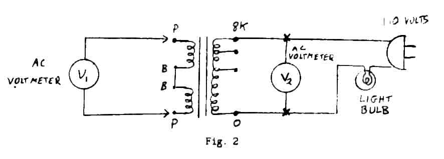
The data from the markings doesn't give the plate-to-plate primary impedance, but that can easily be determined from the information given. You will need an AC voltmeter with approximately a 0-200 volt range, a standard 110-volt light bulb (25 to 100 watts) with socket, a 110-volt AC line cord, and some clip leads. Use the following test procedure:
1. Connect the transformer, light bulb and line cord as shown in Fig. 2. The purpose of the bulb is to protect the circuit by acting as a current limiting resistor in case of a defective transformer winding or inadvertent short circuit in the test set-up.
2. Measure the voltage that appears between the two "P" terminals, and call that voltage Vl.
3. Measure the exact line voltage at the "0" and "8K" terminals. Call that voltage V2.
4. To calculate the turns ratio:
Primary : Secondary = Vl : V2 -or- Primary volts/Secondary volts = Vl/V2
5. To calculate the impedance ratio:
Primary ohms/Secondary ohms = (V1/V2) squared
EXAMPLE:
If V2 (line voltage) measures 120 volts, and Vl measures 150 volts, V1/V2 = 150/120 = 1.25, thus the primary:secondary turns ratio is 1.25:1
Squaring this value, (1.25/1) squared = 1.56; the impedance ratio is 1.56:1 at the 8K terminal.
The nominal impedance of the transformer is: 1.56 x 8000 : 1 x 8000 = 12,500 ohm : 80000 ohm
Thus the transformer was built to run 12,500 ohms plate-to-plate at the primary with a choice of 8000, 6000, or 4000 ohms at the secondary.
With your transformer, make similar measurements, and substitute your actual V1 voltage for the 150 ,volts used in the above example. From your description of the size and weight of the transformer, it is probably designed for something on the order of 250-300 watts of audio.
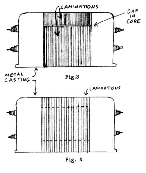
To determine if the transformer was designed to carry DC through the secondary, look at the way the core laminations are stacked (if it is an open—frame type with exposed laminations).
If there is a gap in the core (filled with paper) as shown in Fig.3, it was probably designed to take DC plate current.
If the laminations are stacked as shown in Fig.4, it was most likely designed for use with a modulation reactor to isolate the DC plate current from the transformer secondary.
Even if the transformer is designed to carry the DC through the secondary, it will give better performance if an appropriate reactor is used to take the transformer out of the DC plate circuit. You can expect better bass response and the distortion will sometimes be noticeably less. If the transformer was designed for use with a reactor, do not attempt to operate it with the DC flowing through the secondary. A rule of thumb is to use a minimum of 8 henries for every thousand ohms of modulating impedance. For example, if you plan to use the 6K tap, the reactor should be at least 6 X 8 henries, or 48 henries. The 4K tap would only require 32 henries, while the 8K tap would require 64 henries.
For a complete discussion of the use of modulation reactors, see the article in issues 102 and 103 of this publication.
![]()
Quality Homebrew AM Rig Looking For A Home
Jesse B. Toggweiler, KB4YST, in Louisville, KY, sent some photographs and a description of the homebrew AM transmitter he acquired several years ago. It was built by Carl Rainbolt, W4OIH, now a Silent Modulator. Carl was a camera technician for WHAS-TV, a real engine lathe man, says Jesse.
The RF deck is link coupled in the final. The input coils are an 80-40-20 meter B&W turret. It has 4-125's in the final, but has used 4-400's. The final tubes are push-pull. It is well shielded and forced air cooled.
The modulator deck uses a pair of T-40's or TZ 40's to screen modulate the final. The screen supply is regulated. A special Thordarson screen modulation transformer is used. There is no high voltage power supply.
Jesse had planned to get the rig on the air to operate AM, but has decided not to undertake the project of collecting parts, building a high voltage supply, and getting everything working. He has decided to sell the whole thing to someone who would put it on the air. He is not interested in letting someone scrap it for parts or convert it to a SSB linear.
Jesse also wishes to sell a Hallicrafters S-40 receiver, RME 45, TGID code tape machine, Hammarlund Super-Pro (1930s vintage) ser # 830, and BC-654 parts (att'n Dale, KW1I),
On pages 8 and 9, are shown photographs of the homebrew transmitter. We thought this would be of interest to readers, whether or not you are interested in purchasing the transmitter, Please contact Jesse Toggweiler, KB4YST, 224 Idlewylder Dr., Louisville, KY 40206.
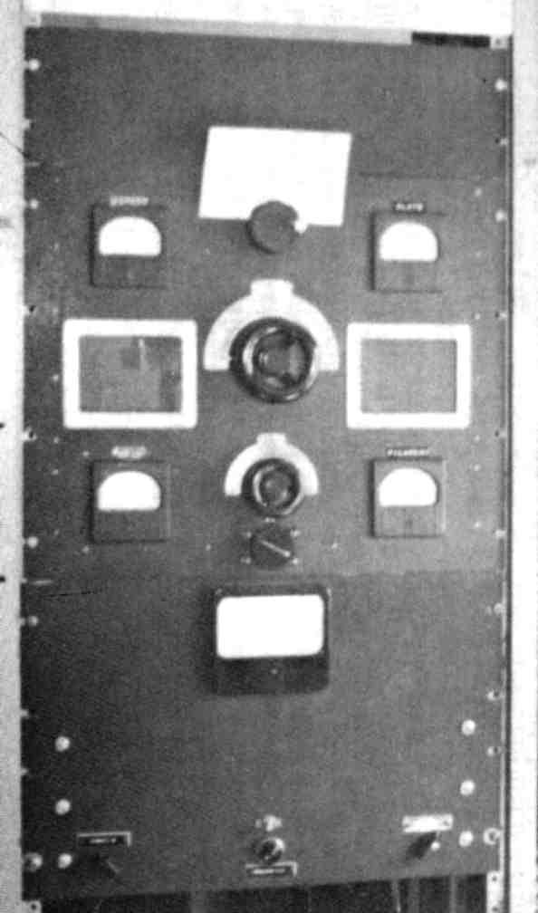
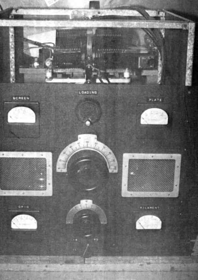
W4OIH rig shown mounted in relay rack with screen grid modulator unit. Detailed description on page 7. This transmitter could easily be converted to plate modulation with the addition of the necessary modulator components.
Close up view of RF deck. In the space above the front panel, the kilowatt plugin coil with swinging link is visible. The meters read plate current, screen current, grid drive and. filament voltage. The final tubes are visible through the screened openings in the front panel.
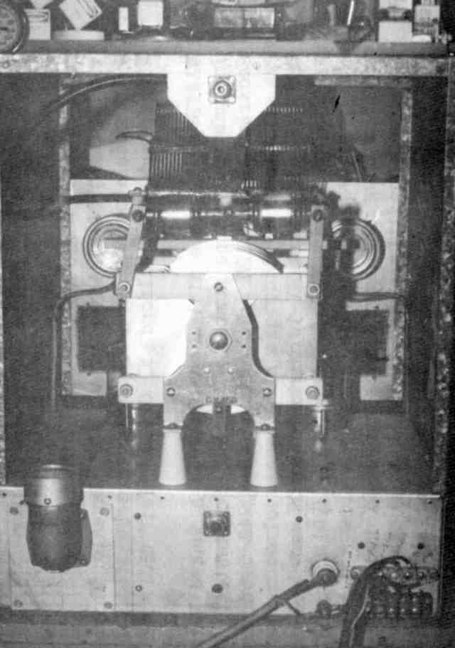
Bottom view of the RF deck. The turret coil assembly allows quick change of grid coil when changing bands.
Rear view of the RF deck shows the butterfly variable plate tuning condenser. The plugin plate tank coil is mounted above, along with fixed vacuum capacitors to extend the low frequency coverage.
![]()
EXCHANGE
(Names removed since these are past issues)
WANTED: HRO 60 dial scales AC, AD. Manuals: Knight 150 xmtr, Hammarlund 4 -11 modulator, Gonset G66B receiver schematic.
WANTED: Complete dial assembly from a junked National NC-100A rcvr. Include your phone number.
FOR SALE: Heathkit HX-10 Marauder xmtr very good condition $125 or BO. You ship or pick up.
WANTED: Johnson Ranger, Johnson 500, DX-100, 32V3, SP600 and HQl70 all in excellent condition.
NEW "SWAP SHEET" PUBLICATION FOR CLASSIC RADIO COLLECTORS: Free advertising; no limitation on any reasonable word length. Yearly subscription (12 issues) $12. First class mail.
![]()
YOU COULD BE USING A SIGNIFICANT READABILITY IMPROVEMENT ON YOUR AM RIG BY SIMPLE PREEMPEASIS AND DEEMPHASIS
By George A H Bonadio, W2WLR, 373 East Avenue, Watertown NY 13601-3829
Part VII
IMPROVING OUR AUDIO FILTER DESIGN
Ed Wetherhold, W3NQN, has been a technical advisor to the ARRL for the past twelve years on passive LC filter design. He has had numerous articles published in the amateur, trade and professional publications over the past 25 years, and some of his work can be seen in the 1993 ARRL Handbook on pages 2-41 to -50, 28-1 to -3, 30-16, 39-12 and 39-13 and Table 41 on page 35-38.
Many years ago (I became W8OMM in 1935 1 made up my own low pass filter nomograph with an overlaying sliding strip marked out in decimal factor values. I put capacitor values sloping opposite the slope of inductor values. Frequencies were vertical and load Z, in ohms, was horizontal. With five stages, of my design, I could get wide ranges as good as -32 dB. However, I had poor continuity, and the flat audio response range before my cutoff frequency had ripples of intolerable and unpredictable amounts. I needed design help.
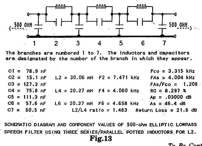
I contacted Ed, W3NQN, about my problems, and he offered to help me to help you. He uses a special BASIC program with an IBM-compatible computer to calculate the component values and performance parameters of the "7th-order elliptic lowpass filter" (ELPF) shown in Figure 13. (The BASIC program used to calculate the ELPF was derived from a program published in the May-June 1988 issue of EMC TECHNOLOGY, Vol. 7, #4.) This particular design was selected so that the inductor values could be realized with combinations of the commonly available surplus "22-mH" inductors.
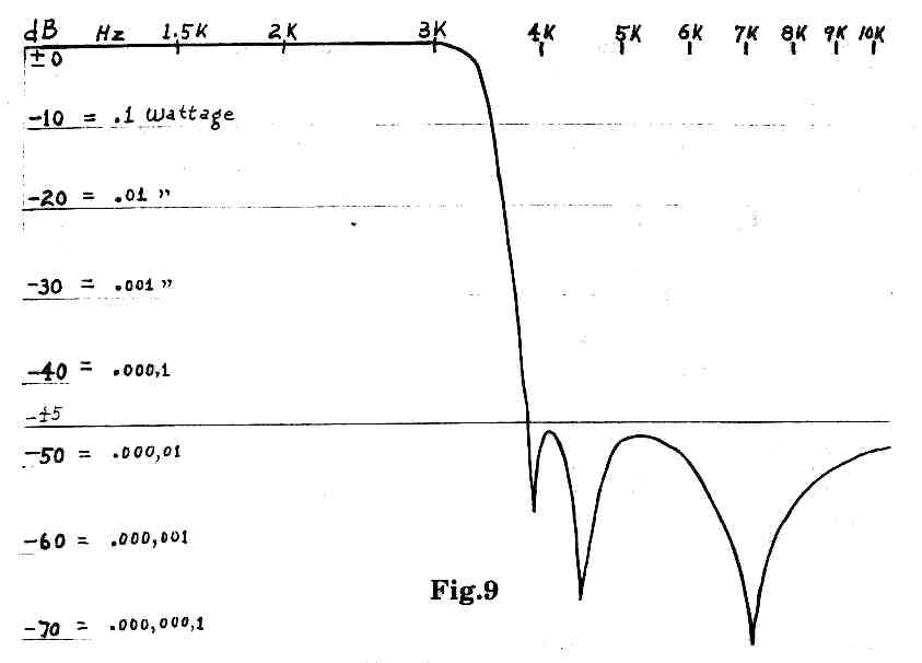
Separately L4 and L6 are each realized with their single nominal 22-mH inductors (each measuring 20.27 mH) while L2 is a combination of a parallel and a series-connected nominal 22-mH inductors. The design "ripple cutoff frequency" (the frequency where the passband attenuation first rises above the peak ripple amplitude, Approx. of 0.030 dB) is 3.315 kHz, and the design frequency where the 46.4-dB stopband begins is at 4.004 kHz.
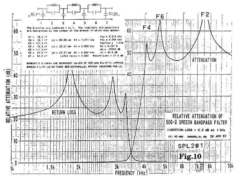
Figure 10, of SPL2#1 (Series Parallel Inductances number 2 design circuit #1 shows the actual measured relative attenuation, and return loss responses of the filter. The actual responses are in good agreement with the calculated values. For example, the measured minimum stopband attenuation, As, agrees very closely with the design value of 46.4 dB. Also, the measured passband return loss agrees very closely with the calculated minimum return loss of 21.6 dB. Finally, the measured peak attenuation frequencies at F4, F6 and F2 all agree, within a few percent, of the calculated values. Figure 9 shows the "upside-down" version.
Not only that giant step forward, but Ed has also worked out a free source of toroids to go along with his circuit specifications for our 500 ohm Elliptical Low Pass Filters (500 ohm ELPF). These are critical designs. That is, we need to come from a 500 ohm source and go into a 500 ohm load in order to realize all the merits of curves. If these Z values in our units are apt to be as much as 10 % different (± as much as 50 ohm) we should use either shunting or series resistors to have closer Z values to 500 ohm. Excellent results depend upon accuracy.
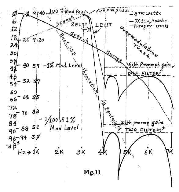
Notice in Figure 11, that the comparison with S Unit values is letting us see what we can do. While our voice strength, above about 400 Hz, goes down at about 6 dB/O, our Preemphasis, at about +6 dB/O substantially corrects this to "flat" between about 300 Hz and 3,200 Hz. What looks like a vertical line from the top, near 3,300 Hz, down, is actually the remarkably steep cut off by W3NQN's filters. Compare this with the Receiver S Unit Scale, on the left. We see that a strong AM signal, at S9 + 40 dB, could have voice energy, or trash, out above 4,000 Hz, at, say, one ten thousandth of this carrier level. That would be at S9. That trash would slope down at frequencies higher than 4,000 Hz away from the carrier. For several channels above and below this, no signals of S9, or less, would be readable. Unfortunately many AM operators have much heavier trash than this and will end other contacts, by unfortunate trashing, as far off as ± 20 kHz of his carrier.
GET CLEAN OR GET OFF
If we want AM to survive we must clean up our act. We have several stages of RF selectivity in the front of our receivers. We have several IF cans of selective filters. We have spent money on enclosing transmitters in elaborately filtered cabinets against television interference (TVI). Now, before our own generated trash pushes ourselves off the RF spectrum, we must use state of the art filtering to greatly reduce our trash. This trash must be considered to be, in crowded bands, frequencies of 4,000 Hz and higher from our carriers. Actually we are using only through 3,200 or 3,300 Hz. In about 700 more Hz we need to drop our audio response by about 90 dB.
We will not enjoy all of those -90 dB because we are limited in where we can economically install filters. We can use one -45 dB filter just before the compressor, in the outboard preamplifier, where it will prevent preemphasized treble, above 3,300 Hz, from improperly activating compression. Here it will also reduce the voice signals, above 4,000 Hz, by at least -45 dB. Further on, in the transmitter, we will use a second filter either on the 500 line or one, of another Z, on the input to the first audio transformer.
HOLDING DOWN THE TRASH
However, there still can be some trash generated by the final modulator tubes. If the tubes are balanced their trash will be mostly of the third and fifth harmonic frequencies, if unbalanced, mostly second and some fourth harmonics along with the above odd harmonics, may show through, but they will be many dB down. A quick test of modulator tube balances is to read the idling current of the pair. Pull the AC plug and wait for tube coolings. Then physically remove one of the pair.
Do NOT just pull off a plate lead and let that still connected screen burn up in a ten second testing. Plug into the AC and read the single tube current, and record it, but do NOT take over a few seconds. The lone screen may melt. Pull the plug, again, and return the first removed tube. Repeat the test for the second tube, alone. Consider a difference, between tubes, of idling current, of less than 5 % as good, over 10 % as poor, over 20 % as spoiling your reputation.
Our new filters will not reduce the modulator's trash. However, the tubes have been, "occasionally" peaking past 100 % modulation drive, spoiling the spectrum for several channels on either side. Now the compressor and safety clippers, in the new outboard preamplifier, will prevent that overdrive, greatly reducing the trash which we used to put out. With balanced modulators we can then be the cleanest and the clearest signal on the band.
No, we will not realize all 90 dB of clearance, but neither will the modulators be driven by audio above 4,000 Hz at stronger than -90 dB. At whatever level the modulators generate their trash, it will be lower than they did before. There will be no significant voice energy in there. Hence the density of the remaining trash will be "time" occupancy thinner. We will have no overmodulation peaks where we have had them trashing widely. We will be accepted as being responsible operators instead of "someone to put-up-with."
SEE THE COMPARISONS
If we compare the advertised spectrum analysis of new SSB we see that they agree with my receiver spectrum analyzer displays. At best, the SSB signals are out to about 8,000 Hz wide at not cleaner than -70 dB, on a two tone test, and a little wider on voice. SSB starts at about 2,200 Hz across the top. We can now start with 6,600 Hz across the top and be down to as narrow as SSB, at -70 dB, by properly using Ed's filters in our setups.
Meanwhile, Preemphasized Amplitude Modulation (PAM) is, essentially, Phoneticalless AM Phone (PAMP). You will hear PAMP operators not using phonetics, while SSB operators find it quite necessary to keep you from guessing wrong. We converse at about 200 words per minute. If SSB has "a good 98 % accuracy" that is only 2 errors in 100 words, or two errors per minute. In ten minutes of conversation, there would be twenty (20) errors! From this we see how SSB needs to use phonetics. Communications can not tolerate only 98 % accuracy. We need and can do 99.9 % accuracy with PAMP.
THE RUN THROUGH CIRCUIT
We need to start with a mike of High Z (say, 50,000 ohm) and match near that into low noise preamplification, then lose up to 99 % of that (-20 dB) in a simple preemphasis control, through one of Ed's design filters, into a compressor. Then a clipper to takes off the "first burst overshoots" then through an output level control, mike cable to the rig. The rig has the frequency response flattened between 150 Hz and 3.300 Hz, onto the air. If we have a receiver with the usual option of a 500 output, we can further enhance receiver clarity by another 500 Q ELPF on the loudspeaker line to cut off all our receiver noises above 4,000 Hz.
AS WE SEE IT ON PAPER
We have made a few "mid-course corrections" and we are coming out in better results than when this story was begun to be written. Even the receivers are getting into the act, in making the reception cleaner and clearer.
The transmitters are with shorter skirts of trash, just about as good as the present new SSB state of the art.
Fortunately, the human curve of drop off of voice energy, with higher tones, is useful. We are using up that drop off in a manner which is to put in a significant build up of that same treble. Then we are using the average total selectivity of AM receiver IF selectivity to reduce that built up treble. This is to sound close to a normal energy spectrum. Meanwhile this preemphasis happens before the path noises are added. Then the receiver reduces both the excess treble and the path noises at the same rate. This gives us both realism and readability. Meanwhile distracting noises, beyond the articulation spectrum which we are using, are further removed by audio filters. Two are in the transmitter and a third in the receiver.
Unplanned is a benefit for operating on 160 & 75 meters. This is where radiations from TV receivers sizzle an AC signal at every 15,750 Hz across the band. In effect I am expecting that daytime operations on 75 & 160 will be able to cover 140 % of the former satisfactory daytime range. This means twice the population is available to answer our calls in the shorter daytime ranges. We fit neatly with two PRAM (Preemphasized-Deemphasized Amplitude-Modulation) signals between sizzles, which are 15,750 Hz apart. These help in locating calls and in avoiding AC-TV-QRM.
WHAT'S NEW AND DIFFERENT?
We do not want to be on the way out, as did the old spark gap transmitters, with our too wide AM signals. If spark could have narrowed down to, say. 100 Hz wide, some might even
still be on the air. Regardless, AM has, generally, been much wider than necessary. The SSB manufacturers do claim that their two-tone 3rd order harmonics are down to a -39 dB. This would have their trash, between 4,000 Hz and 8,000 Hz at not stronger than -39 dB, of their peak signals. We, on AM, should not be playing "catch up." We should be leading so that others would want to catch up to us. We can.
With our first ELPF (Elliptical Low Pass Filter) we both chop our highs off just above 3,200 Hz, by better than -45 dB, above 4,000 Hz, and we reduce our overdrive of treble into the compressor. About six stages later we go through another ELPF or LPF to reduce the clipping and the harmonic trash of those several stages. On medium powered stations, with an LPF, the second filter will peal off trash, which seldom comes up to -25 dB, by another -10 to -45 dB, for a net range of -55 to -90 dB.
With the higher powered stations, with 500 ohm lines for their audio drive, their second ELPF will be -45 dB for everything above 4,000 Hz. The trash loss numbers read beyond
-90 dB, here, so, only the trash of the final modulators will have any significance. The compressor is keeping the modulators from being overdriven, into distortion, so their trash is the limiting factor. If they are well balanced their second, fourth and sixth order of harmonics will be extremely low.
The real difference is that we have not been filtering our trash. We have been throwing our trash out onto the air. If we tried to operate receivers with no better selectivity than our transmitters, we would have very few contacts, and none of them would be in crowded conditions. Belatedly we are advancing. Its a big step forward, but if we do not do it soon, we can expect serious troubles with this problem.
If we want the improved readability with the above audio processing we are going to increase our trash outside of our usable voice spectrum, while inside of our audio stages. However, these two levels of filtering will correct us to be so narrow that when we are tuned in we will be somewhat of a surprise. We are so used to hearing trash as we tune towards a strong AM signal that we will be surprised to find a strong signal there with which we could not notice it putting unreadable trashing further up or down the band. Beyond the spectrum that we are using we will be cleaner that many SSB signals.
Then notice that we are on "Phoneticless Phone." We are not asked for repeats. We are not asked for phonetics. We have the most readable voice signals on any spectrum.
AN ELPF FOR THE RECEIVER ?
We all recognize that SSB receivers have a narrower IF selectivity, substantially listening for a width of 2,700 Hz and cutting off sharply. Meanwhile, we need to listen for 6,400 Hz and cut off sharply. We accept a receiver band that is 237 % as wide. While SSB receivers hear trash full strength up to 2,700 Hz, AM receivers hear trash in strength up to 6,400 Hz, due to our wider IF's, to receive two sidebands.
However, AM receivers do slope down, ideally, about -15 to -20 dB, by the high end, 3,200 Hz. We want to hear, on AM, only through 3,200 Hz. However, due to using two sidebands, we go to double that. The most desirable way to rid our audio from all that high treble trash, above 3,200 Hz, (not heard on a modern SSB receiver) is to install an ELPF between the receiver's 500 ohm audio output and an outboard transformer of 500 ohm to the voice coil Z, about 8 ohm. See Figure 12.
I advise the use of a DPDT switch to put the filter in and out because you will want to see the good that it does, at least a few times. Both line noises and lightning noises are helped by this, as well as trash sidebands. In effect your receiver s ELPF, only in noisy conditions, will double the effective wattage (+3 dB) of the incoming signals, against those noises.
While the difference in noises onto a strong clear signal with the switch in or out is insignificant, the difference in copying critical information in noise or interference or static is significant. Meanwhile the difference in the fatigue of listening through useless hash or trash is a factor in when you or I quit the air. It is difficult to put a dollar value on this factor.
WHY ARE 2 FILTERS NEEDED?
We can see in Figure 1, the upper portion of line D where we are building up our treble about as fast as our natural voice treble is falling off. Thus we are about to modulate near 100 % with any frequency above 707 Hz as below 707 Hz. In the past we have been using circuits running the treble gain down from the level near 1,000 Hz. This has been averaging about -6 dB at 3,200 Hz.
Now we are going to be anywhere from + 10 dB to +20 dB above flat, near 3,200 Hz. Adding these is + 16 to + 26 dB more energy, above 3,200 Hz, which we may refer to as trash because it will be unusable.
Actually, to get the upper rise curve of line D to be straight, we have to cut off the top sloping portion, which runs about another + 6 dB. Thus, at, say, 6,000 Hz, we are hiding another + 6 dB of gain. Therefore, we need to cut back as much as -22 dB to -32 dB, just to keep as clean as before, which level, in practice, has not been good enough.
We do this in two very sharp filters. One is in the preamplifier-to-preemphasis control, to give better operation of our very effective compressor. The other is usually in the output of the driver stage to the final modulators.(*) Each of these two are able to reach about a -45 dB above 4,000 Hz. Each passes 3,200 Hz with very little loss. After the trash from the final modulators, we should still be (who knows ?) much better than -50 dB (a loss of 100,000: 1 in wattage) for all above 4,000 Hz.
*EDITOR'S NOTE: This is recommended only when the modulator is running class-A or AB1, and the driver transformer secondary is loaded with resistors to properly terminate the filter. With a class AB2 or class-B modulator, the filter should be placed at the input to the driver stage, with the proper terminating resistors. Class AB or B grids present a varying load impedance to the filter, resulting in improper filter action and tremendous splatter and distortion, if the filter is inserted between the driver and modulator grids.