
Issue #106
Scanned and OCR'ed by Mike Warren, W5MAZ
![]()
AM International Formally Unveiled at Dayton Forum
AMI was formally announced at the Dayton HAMvention on April 24, 1993.
AMI is a worldwide organization of amateurs interested in the enjoyment, promotion and preservation of the use of AM phone on amateur radio frequencies. AMI will be led by a President aided by a Vice President and Treasurer. These officers and a group of seven Regional Directors will form the governing Board of Directors. The seven AMI regions are currently being finalized, and officers and directors currently in place are volunteers serving in an interim capacity. Nominations and elections will be held in the fall so that elected officers and directors will be in place as of January 1, 1994.
AM enthusiasts worldwide are encouraged to join AMI by sending $2.00 (U.S.) to receive an attractive AMI certificate, brochure, copy of AMI by-laws and list of officers and directors. Groups of amateurs interested in AM in other parts of the world are encouraged to become self-governing affiliates with AM International to stimulate AM activity in their regions. All News will be published in The AM Press/Exchange and Electric Radio. Financial reports will be published quarterly.
Many AMI promotional, event and operating activities will be driven on a regional basis. Periodic AMI-wide operating events will be announced.
Your ideas are always welcome at AMI Headquarters. If you want to be more involved contact your Regional Director. For more information, write to:
AM International
Box 1500
Merrimack, New Hampshire 03054-1500
![]()
Another Successful AM Forum at Dayton
The annual AM Forum is becoming established as a regular fixture at the Dayton HAMvention. As in previous years the conference room was filled to standing room only. This time the Forum Coordinator noted that we need a larger room for next year! Although cramped for space, the room was comfortable, thanks to the ceiling fans installed a couple of years ago.
The Forum began with Dale Gagnon, KW1I, who announced the formation of AM International. Details appear on the front page of this issue. Dale explained the reasons behind the formation of a new broad based AM organization, and passed around a sample AMI membership certificate. Dale was careful to give the organizational details without creating the dry "business meeting" atmosphere that kills interest at so many local ham clubs, using an overhead projector and an attractive, professionaly printed brochure that was passed out to those in attendance.
Following the AMI unveiling, which lasted no longer than ten minutes, Dale presented the slide show, "Amateurs and their broadcast transmitters," featuring pictures of amateurs and their AM stations using converted broadcast transmitters.
The slide show was followed by a video presentation featuring an actual QSO between Paul, WA3VJB and Gary, N2INR. As each operator transmits, the viewer is surrealistically alternated between the transmitting and receiving sites, to see each transmitter in operation and then hear the same transmitter at the receiving end of the QSO, comparing the "studio" sound to the sound at the other receiver. Paul, who was present at the Forum, explained how the video was produced, and that it would ultimately become part of a promotional video for AM.
Finally, the Forum was turned over to Don, K4KYV (Editor and Publisher of AX P/X. Don moderated a panel discussion featuring Andy, WA4KCY AMI’s Southeast Regional Director), Dale, KW1I and Paul, WA3VJB (co—author of the AM article in February QST). Discussion included AMI in the Southeast, the AM articles in QST, and numerous concerns expressed by AM’ers in attendance at the Forum. Paul elaborated on the mystique of the "AM Radio Network" referred to in the QST article and often heard mentioned over the air from stations in the Northeast.
Unlike previous years, time allowed those in attendance to get acquainted in person after the conclusion of the formal program, before being ushered out to make room for the next scheduled forum in the conference room. Vein, WA0RCR, net control for the Gateway 160 meter Net and noted for his bulletin service on 1860 khz. AM suggested that this frequency be included in the published listings of "AM frequencies."
As in years past, some of the AM’ers got together later in the evening at a local pizza parlour. Notably absent were some of the Southeastern gang who explained they weren’t being antisocial, but that they just didn’t like the smell of pizza. Most of these hams were able to meet and chat with fellow AM’ers the next day at the fleamarket, however.
Thanks to everyone who attended and see you at HAMvention ‘94!
![]()
Power Level Waiver Denied
The FCC has denied a request for a waiver of the 1500 watt p.e.p. AM power limit. Dale Gagnon, KW1I had asked for the waiver after the Petition for Reconsideration of the original rules change was denied. The FCC said Dale’s latest request "has not shown that his circumstances are unique nor has he presented any facts that would warrant a waiver." Dale wanted the waiver for his own use, to legally operate AM at the historic power level.
Dale explained that he did not anticipate a favorable ruling from the FCC. While the Petitions for Reconsideration were pending, he contacted his representatives in Congress, and one of their legal advisors suggested that a Request for Waiver might be more effective than the Petition for Reconsideration. Dale went on to explain that the purpose of this request was to avoid leaving any avenue of relief unexplored.
The mainstream amateur radio press, including QST, has reported this story, towing the FCC party line without question. Most reports described the request as "to waiver the amateur 1500 watt power output limitation." One publication alluded to a special exemption allowing AM’ers to run "more power" than users of the "1300 other emission types" in the amateur service. The headline in W5YI REPORT read: "The diehard AM’ers still feel they should be allowed higher power amplitude modulated (AM) emissions in excess of the 1500 watts PEP maximum permitted in the amateur service." The article went on to describe the original petitions to make the grandfather clause" permanent, as requesting to "amend the AM amateur power limitations," implying that the issue was initiated by AM’ers wanting to run higher power than users of other modes, ignoring the fact that the FCC arbitrarily reduced our power levels while allowing certain other modes to run up to twice their historic power levels, and that the AM community merely requested to correct this inequity initiated by FCC bureaucrats in an ill—conceived effort to "tidy up the rules."
Unfortunately, the AM community seems to have given up on the power issue. Little discussion is heard over the air, and AM P/X has received only one or two letters on the subject from readers since the FCC denied the Petitons for Reconsideration. AM’ers seem resigned to defeat, and most disappointingly of all, AM operators are heard over the air cheerfull describing their power level in terms of P.E.P.!
This is a matter we cannot let die! The FCC’s Private Radio Bureau arrogantly counterattacked with blatantly misleading arguments every time the AM power matter was brought up before members of Congress, the Bush Administration, or the FCC Commissioners. The ruling sets a terrible precedent for arrogant government; this agency must be taken to task for being less than honest in the manner in which they handled the issue.
The AM community has the documentation to prove our point. We must continue to bring this up at every opportunity and demand simple fairness from a government agency paid for with our tax money. Remember, Haller and Johnston will not hold their positions at the FCC for ever, and they might even be replaced by someone reasonable and fair-minded!
![]()
Open Forum
WA3VJB Wednesday, March 31, 1993
Annapolis Radio
Mr. Jack Greenwood
Radio WB7QDN
Box 249
Wolf Point, MT 59201Dear Mr. Greenwood:
I’m glad you took the time to write an editorial letter published in April, 1993 QST magazine, in response to an article I co-authored about the use of AM on the ham bands.
Your point is unquestionable that AM takes up twice as much space as SSB What I would like to discuss with you is whether the spectrum we use is "wasted" as you have claimed.
You advocate using modes that conserve space on the limited frequencies we have; that is a worthwhile goal. .But it is not the only goal of the Amateur service, nor is it even the top goal. Mr. Greenwood, the ham bands are not a primary communications medium, where maximum band occupancy is part of the structure, as in allocations for commercial frequencies.
Quite a long time ago, amateur organizations such as the ARRL pushed spectrum efficiency as a high priority because the ham ranks were stagnant in size and a little lacking in mission—creating a perception we were vulnerable to losing portions of our allocations. Conditions have dramatically changed in the past 20 years.
The struggle SSB faced for acceptability over AM as a "mainstream," or predominant mode has long since been resolved. AM has become a nostalgic little specialty that serves very well the mandate for the Amateur service to nurture a skilled pool of technically proficient radio operators. You’ll find a lot of homebrew activity and hands-on experimentation among our ranks - - far more than among those who buy and use rigs that are far too sophisticated for most ham workbenches to handle without great risk. Yet the technical experience one gains from building, restoring and using older rigs translates well to modern technology, at least as a confidence builder if not a direct understanding of today’s circuitry.
By opening a claim of wasted spectrum, you put at risk all Amateur activities that fall outside the definition of emergency, essential communications Chit-chat so commonly found on SSB, packet, and FM might be considered just as wasteful, as well as DX’ing contesting, cross-band repeaters. . . the list goes on and on.
And as for increasing the ranks of hams, I’d be glad to mail you a list of people who, as SWLs, happened across the only intelligible communications they could pick up on the HF ham bands - - those of us on AM - - and later have become licensed Amateurs. The list I’ve collected from inquiries of my own station totals about a dozen In the past few years alone.
There have been anti-AM petitions of the FCC over the years reflecting your sentiments. Yet each has been rejected by the Commission as the agency affirms its definition of the Amateur service and underscores why we have frequencies allocated to us. The theme is one of experimentation. You might think there’s not much to learn about AM anymore, that perhaps we are re-inventing the wheel.
Yet you might also be surprized to learn that In the past 15 years a great deal of discovery has taken place involving AM techniques on both receive and transmit that have helped, for example, the broadcast industry. Pulse Duration Modulation is a recent invention to improve AM transmitter efficiency and conserve electricity. It was brought to market by Harris/Gates, but It was refined from early paperwork design by people on the ham bands. Synchronous detection has been around for years as an improved reception method; hams have applied advanced technology to make it work even better than any vacuum—tube variety.
I’d like to hear your definition of "communication" that you say is an opportunity curtailed against others by those of us on AM. Because I would insist, for the sake of my response to you, that you justify such communication in terms of what it can contribute to the hobby. At worst, hams have always run the risk of looking like so many old white men with am exclusive club—at least to outsiders. At best, you might agree with me that activities on the ham bands are easily justified if they meet the criteria long established within our ranks and by Federal decree.
No one is calling for a return to AM as the main mode hams use to communicate on the shortwave bands. And to my knowledge, even the most radical of AM’ers have yet to call for any rulemaking petitions to ban SSB as a non-essential mode based on the overwhelmingly trivial conversations a strong critic might perceive.
No, it seems the middle ground has the most support across the broader Amateur ranks. And the League is doing a better job these days trying to represent all interests in the hobby, to the exclusion of none and without favoritism of any.
A final point—regardless of what mode through which a newcomer is first exposed to Amateur radio, notice how we all learn quickly the importance of being ready to supply public service communications when needed. That’s perhaps the biggest justification for our hobby, and I believe that encouraging activity in ALL modes available to us has the effect of encouraging the hobby overall.
I hope to hear from you with some elaboration on your thoughts, and some reaction to the ones I’ve offered you.
Sincerely,
Paul S. Courson
WA3VJB
3941 N.W. 35th Terrace
Ft. Lauderdale, FL 33309
8 February 1993
Editor, AM Press/Exchange,
Just a brief report on the Miami, Florida hamfest held 6-7 February.
As I walked into the flea market area, the first thing I spied was an NC303 with speaker and manual for $100. Condition very good with a few scratches. About 2 seconds later I bought it. This will go very nicely with the Valiant II that I acquired prior to the hamfest.
There were two very nice Hallicrafters SX-71s with matching speakers... $120 and $150. I was sorely tempted! One Johnson Viking II CC in excellent shape.. .$150.That is the end of the good equipment. The rest of the boat anchors were in rough to fair condition. A couple of National NCl83s, one painted green; Heathkit mobile twins (Commanche and Cheyenne); beat up, rusty, DXl0O and Viking I; a fair Heathkit Mohawk, price unknown; and several general coverage receivers. Not a lot of AM gear for such a large hamfest.
Interestingly, the number of SSB rigs offered was very small. Most of the flea market consisted of test equipment, both junk and late model stuff, non amateur related things such as scissors, jewels, pens, and even a semi-bald, used tire!
Though the new equipment vendor section has never interested me, I noticed that 90 percent or more of the vendors were computer companies, both hardware and software. If this hanfest is indicative of future ones, it’s a sad situation for RADIO enthusiasts.
Well, hope to get the Valiant on the air soon. Looking forward to working the AM gang again. And yes, the NC303 works FB !
73,
John
W4KYL
![]()
Silent Modulators
With deep regret, we announce the passing of two well known AM’ers.
Bernard Koby, K5MZH, known on the air as "Koby", died at the age of 71 on April 26, 1993, in San Antonio, TX, when he suffered a heart attack after his fifth heart by-pass operation, according to his family. He was a retired 30-year veteran of the San Antonio Police Department.
Koby was well known on 75 m. AM in the ‘60’s and early ‘70’s, and reappeared on AM in the mid ‘80’s when he discovered many of his old friends were getting back on AM. He was born in Dijon, France in 1922, and moved to the United States with his family at age 13. He always maintained his command of French, and could sometimes be heard on 75 carrying on a QSO in that language.
He was a Veteran of the Army Air Corps during World War II. He flew cargo planes and was once shot down near the Philippines. His police work included an assignment with the intelligence bureau where he investigated narcotics, white-collar crime and terrorist crimes. Working with New Orleans Detective and best-selling author John Dillmann, Koby helped convict the murderers of Patricia Ann Giesick who was struck by a hit-andrun driver during her honeymoon in New Orleans. The story was told in Dillmann’s book "Unholy Matrimony", in which Koby was featured.
Koby was an accomplished artist, crediting his interest in oil painting to his uncle who was also a painter. At least one of Koby’s paintings was presented to Ladybird Johnson and reportedly hangs at the LBJ ranch. Koby also played the harmonica and piano, according to his daughter.
A man of many talents, Koby will be sorely missed by his amateur radio friends, as well as many others who knew him through his interests outside of amateur radio.
Fred Huntley, W6RNC, passed away February 8 in Nevada City, CA at the age of 75, following an extended illness. Fred had contributed articles to this publication describing various pieces of equipment, including photos of his famous "Kelvinator Kilowatt," which used a unique cabinet made from an old refrigerator. The rig used 250TH’s in the final and used a scheme of plate modulation that did not require a modulation transformer. A colour photo of the same rig was later featured in QST.
Unlike many of today’s AM’ers, Fred did not "get back into AM" in recent years. He was one of the few who never left AM to begin with, and continued operating the mode during the late ‘60’s and early ‘70’s, when nearly everyone elso had left the air or gone SSB
The AM community has suffered a loss, and Fred will be missed by those he talked to over the air as well as those of us who knew him through the articles he published.
Another Silent Modulator report appears in Meet the AM'ers.
![]()
MEET THE AM’ers
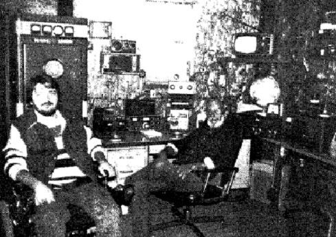
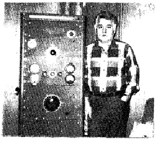
Don Scott, WA4UGR (right) is shown with his son Tim, KD4DVH (left) at the ham station. Right to left is shown ths Johnson Valiant, SX-71 receiver, homebrew 813 amplifier, scope, wattmeter, antenna tuner. FTlO1EE, homebrew antenna tuner. "757 slopbucket rig and power supply. The rig in the tall cabinet is a homebrew 4—lOOOA final with a pair of 813’s connected as zero-bias class-B triode modulators.
The homebrew rig is shown with the door open to expose the front panel layout.
Just as this article was being written, Don became a Silent Modulator. He suffered an unexpected heart attack at work on Friday, June 8 at 4 PM. He was a lineman for the power company, and was up on a pole at the time. His voice will be missed by all who know him through his AM signal on 180, 75 and 40 metres. Our deepest sympathy goes to Don’s family.
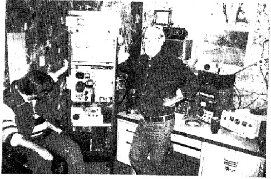
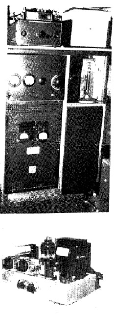
Coy McGinnis, KA8STS is shown beside his homebrew rig using a 250TH final with a pair of 304TL’s as modulators. Coy’s 500 watt homebrew rig with 813 amplifier and 811A class-B modulator. A Ranger II is used as a driver for the amplifier and modulator.
LOWER: the "38 Special" which is a homebrew transmitter using a xtal controlled 6AG7 driving a single 6L6 It runs 38 watts input (380 volts at 100 mills). Coy is presently working on a modulator for it.
![]()
Longer Life for 6146’s
WA4BNO sends the following, which he found in RCA Ham Tips, June, 1958. The article gives a dozen do’s and dont’s to give maximum life for this type of tube. These hints should be useful for other tubes as well.
- Hold the heater voltage to as close to 6.3 volts as you can measure at the tube terminals.
- Provide for adequate ventilation around the tube to prevent tube and circuit damage caused by overheating.
- Keep shiny shielding surfaces away from the tube to prevent heat reflection back onto the tube.
- Design circuits around the tube to use the lowest possible value of resistance in the grid circuit and screen circuit.
- In high frequency service, operate the tube under load conditions such that maximum rated plate current flows at the plate voltage which gives maximum rated input. (It is left to the reader to figure out exactly what they mean here. - Ed.)
- Use overload protection in the plate and screen circuits to protect the tube in the event of driver failure.
- See that the plate shows no colour when operated at full ratings (CCS or ICAS conditions).
- Reduce B+ or insert additional screen resistance when tuning under noload conditions to prevent exceeding grid-No.2 (screen grid) input rating.
- Maintain tuning and loading adjustments precisely so that the tube will not be subjected to excessive overload. The 6146 is a high-gain, highperveance tube and can be more easily overloaded through circuit misadjustments than older types of tubes not having such characteristics.
- Use adequate grid drive, keeping within the maximum grid-current and screen dissipation ratings of the tube. Too little grid drive can cause high plate dissipation.
- Make connections to the plate with flexible leads to prevent strain on the cap seal.
- Operate the 6146 within the manufacturer’s ratings as shown in the RCA Transmitting Tube Manual, ARRL Handbook, or other trustworthy publication.
![]()
EXCHANGE
(Please
note this is a past issue. DO NOT contact people in ads!)
B.S.
KD7xx ESTATE SALE
Yvette Duncan, widow of Phil Duncan, KD7xx, has decided to sell Phil’s ham equipment. She had kept it since Phil’s death in case their son might be interested in using it, but she has concluded that he is more interested in computers than vintage radio equipment. The money she receives from the radio equipment will be used to upgrade his computer system.
The equipment is still mostly intact, Just as Phil left it, and has been in storage in a garage in Colorado, where the low humidity should have resulted in little or no moisture damage.
The equipment consists of Phil’s homebrew plate modulated AM transmitter, National HRO-5O receiver, plus lots of books, tubes, parts and test equipment. The family would like to give this equipment a good home, where someone would appreciate it. She would like to sell everything by the end of June, if possible. Contact Yvette Duncan, (303) 225—8055, Ft. Collins, Colorado.
Yvette says you may call collect if you are really interested in purchasing some or all this equipment.
WANTED
Any information or papers on RCA type RM-174 115 VAC power unit for ET-8050 equipment manufactured by Radiomarmne Corporation of America, NY, NY. This power supply uses two 866A tubes. Also looking for Collins 10" speaker in matching cabinet for 74A-4 receiver, meter for Heath Apache, mint Heath Mohawk receiver. WA4KJK, Jerry Miles, 3349 Percy Priest Dr., Nashville, TN 37214
REQUEST FOR INFORMATION
I am totally blind, and a friend has been helping me restore a Viking Ranger. We are looking for a safe way to gain access to the meter readings. I have a tuning aid which emits a tone. The tone changes as the current flowing through the meter changes.
The problem is that the Ranger’s meter is in the high voltage circuit. A rather unpleasant experience with a similar circuit about 20 years ago tells me that connecting my. tuning aid to such a meter is not wise. I am seeking a circuit which will allow me independent access to the meter functions at a safe voltage level. Can anyone offer me any solution other than trading my Ranger for a rice box? I will appreciate any assistance readers can offer me.
Mike xxx, WB5xxx
FOR SALE: R392 with power supply and manual $250.00. Manuals: Invader 200, Valiant I, $15.00 each. Hickok 225 VTVM Heath IM-13 (needs work) $15.00 each. Transformers: Ranger LV choke, $15.00. Invader 200 power transformer, $25.00. Valiant HV transformer, $25.00. Valiant HV choke, $20.00. Valiant Cabinet (outer shell), $20.00. I will ship. Herman , KDxxx.
FOR SALE; W2xxx is moving because of health reasons, and the following equipment must go to a good home. Knight transmitter, SX-28 receiver plus some homebrew stuff. Also mint condx 1928 Zenith broadcast receiver.
![]()
YOU COULD BE USING A SIGNIFICANT READABILITY IMPROVEMENT ON YOUR A M RIG BY SIMPLE PREEMPHASIS AND DEEMPHASIS
By George A. H. Bonadio, W2WLR, 373 East Avenue, Watertown NY 13601-3829
A Series on Amplitude Modulation Improvements
Part V
In Part IV the concept of "B values" was reviewed, and components and circuitry used in the audio stages of the transmitter were discussed. In this installment, the procedure is explained for determining the total audio response of the audio section of a transmitter. This should prove useful to anyone wishing to evaluate the audio performance of a transmitter, regardless of whether the modifications described in this series are being considered.
MAKING MEASUREMENTS
Any skill is easier with appropriate tools. Some that we need are not always available in every shack. Make agreements with other hams, station engineers, repair servicemen, to use any tools which you need but do not have. Many service shops still keep old scopes, audio signal generators, meters with a dB scale, etc. around, which are too good to discard, but difficult to market. Take good care of them. You may want to bargain for them later.
We do need to make a high number of separate readings of our transmitter audio frequency response. Otherwise we will not know what we have, or what we have done. These readings we will plot on copies of a graph such as was supplied to you here, earlier. Do not use the original graph for readings; make extra copies.
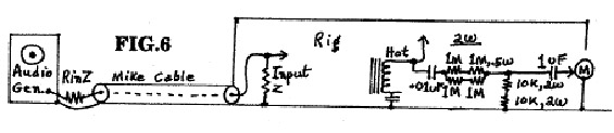
The preferred layout is in Figure 6 to start with an audio signal generator. Connect it through an R = your input R of your mike circuit, typically still 500,000 ohm to 1 M ohm to G. Notice that we need to include your entire mike cable, due to its significant C value, undesirabley bypassing treble to G. The rig is out of your cabinet. Pull your rig’s AC plug. Use the same socket for your soldering tool, so that you can not have them both plugged in at once.
Find a terminal that has your high side of your modulation, before it reaches your tank. Connect a voltage divider from there to chassis. Notice its construction. If you want to keep the resistors cool, you put in a series blocking C of about .01 uF (10n). It must have a V rating of at least twice your DC V. For each 500 V of plate supply voltage use 1 M ohm (1,000,000 ohm) of about 2 W (watts) dissipation. A 1,000 V rig would need two assemblies of a megohm. Four, each, 1 M ohm half W R’s, in series / parallel, will still measure as 1 M ohm but for 2 W.
VERIFICATION IS BEST
Take the time to quickly check every resister ® on your ohmmeter before using it. At least check every C for series DC open, or leakage. If you have acquired the use of a C tester, check the C for leakage at the peak voltage range you expect to use it. If it is an electrolytic or tantalum, check it for power factor. Reject any C with a power factor reading of over 5%. Do check new ones, too.
In the voltage divider, on the G end, use two each, 10,000 ohm at 2 W in series. The upper R’s will run warmer that the lower. The output V will approximate 20 V peak to peak, fine for a scope or a VOM (Volt,OhmMeter). If you must have higher voltage for a meter, add another 2W 10,000 ohm R into the lower end. The output C will not have 50 V on it, and it must be near 1 uF (1,000n), so we can use a Radio Shack 200/250 V C. This should let us see any 60 Hz hum as it is.
DUMMY LOAD
We must have an RF dummy load. It should be from a lamp(s) soldered to coax, and operating, in view, across the room where it can not start a fire. Always operate the rig, when testing, at the manufacturer’s. ratings. At those ratings adjust for the maximum bulb brilliance, however it glows. Unplug the rig.
REFERENCE POINT
Turn the mike gain way low, but not off. Connect your dB scaled meter to the chassis (G) and the 1 uF C, as in Figure 6. Set out your 4 or more colored pens near your graph paper. Place your meter in easiest reading position for when you are tuning the audio generator, while you have a pen in you other hand and don’t have to move to mark your graph. Turn on your generator for its lowest level of output. Set its dial for bout 1,000 Hz. Plug in your rig. Light your dummy. Slowly turn up your gain control while watcbing your meter. Monitor in your receiver.
If you find no usable signal, set your gain to halfway. Move your generator output up, slowly, to find a setting where you can read output. You may reach full drive with the generator at part way up on its .01 V (one hundredth of a V) scale, so don’t rush into it. If you have a scope ready it should read what is going into your meter. Generator tones are pure. Watch and listen for distortions.
On the meter you should be using the lowest AC Volts scale that it has. When you find a signal try to readjust settings so that you rig’s gain control is about half on. Use this for controlling the level to an exact dB mark.
Set a signal so that you are near half way on your diB scale, at 1,000 Hz. Sweep your generator to its used scale limits (usually 10 to 1) to find the frequency of greatest response. If it is the original circuit it is probably between 1 K & 2 K Hz. If it has been "fixed-up-with-bigger-C’s-to-get-betterquality" you may find the peak anywhere, but probably much lower, and, on the air, not very readable against any noise or interference.
Read your dB meter scale. Its top dB mark may be +12 or +2 or +22. Use that number for the top dB level of your graph. Number the lower horizontal lines, down one side, as 2 dB less for each line. Notice that you go below zero, with - levels. Any dB change is the same ratio, regardless of the starting level.
I recommend that you do not try to read every few cycles. Try marks at the frequencies marked at the top line. At times when you are making changes with the bass you may want only the bass and a reference level at 1,000 or 3,000 to prove your levels. With enough points, unplug your power. Draw in smooth curves between the points and mark both ends as ORIGINAL. Change color for the next curve. Number each curve in order, at both ends, and give any data about it at one end.
THE WHOLE PICTURE
You should extend your curves to the ends of the chart. The high end will be used in proving that your filtering is working. Take a light color and draw a line from the lowest level left corner, upwards for 6 dB, at a frequency that is twice as high as the starting Frequency. This is a representation of the gain increase of + 6 dB/O (+ 6 dB per Octave, or twice frequency at 4 X the power). Continue the - line, lightly, across the paper. Your preemphasis is to duplicate this. However, it cannot until you have flattened you rig’s curve.
Draw a similar curve, but reversed, starting high and going down by 6 dB at twice the frequency. When you see slope lines in you original curve, compare them with these straight lines. An original rise or drop which is twice their rates will have at least 2 C values to be corrected.
SOME LIMITS
Do not run the signal level so high that your modulators show more than a slight increase in current. These sets are built only for voice average power so a sustained high current on the modulators will overheat something.
My 1950 assumption that my Collins 32V2 could modulate to 100 % on any tone between 300 and 3,000 Hz was wrong. It would at 1,000 Hz, but it was far short at both end frequencies. Any classical rolling off of the frequency response will reduce the capability of that set to be able to reach 100 % on those tones. Hence, what we are doing is bringing the capability of modulation up to full all across the usable audio spectrum. We will need this to get the job done.
If you try to drive your set by a steady tone, to modulate 100 % on your range that is more than a few dB down, you may overdrive something, and regret it. Stay cautious. You should have heavy lines, vertically, at 150 and 3,300 Hz. You need all of these.
Do not make the mistake of believing that you need to extend your deep, deep bass down below 100 Hz. Most ham receivers will lose that range in 4 C’s and one transformer, then listen for it in a too small speaker in a too poor baffle at a level which further depreciates bass. Unplug your set.
GET YOUR B VALUES READY
You have had time to calculate the B values which you have and which you want to change, and time to buy them. Now it is time to prove that they are what you want. Use test leads of a set which is not flimsy or weak jawed. If you need more light, use the 30 W reflector flood in a slim push button socket on zipp cord. Look for a big C that is to be eliminated. Cut its more exposed lead at its solder joint. Bring this opening out on 2 clip leads. Join the 2 clips on the bench.
Plug in the rig. Turn it on. Read either the corresponding 150 HZ or the 3,300Hz level, in dB as it has been. Open the test leads after turning the set off, then turn it back on. With the second color pen mark that level and some readings left and right of that one. Extend the curve only as far as needed to show effects. Pull the plug.
Disconnect the clip leads. Either remove the unneeded part or bend its cut lead so that it can not fall into some contact. Any other part that you are curious about you can test this way, singularly. Now you feel justified in making several changes to only one test. Gradually you will find your curve flattening. Make all the rest of the B changes that you can, a group at a time. Then test. Then unplug.
THE LAST FEW DB NEEDED
With some rigs there are so many mismatched transformers and other special circuits that you may find your flat line is drooping at one end. If you have as much as a 1 dB slope per octave, you should try to correct most of it. If you have enough gain, use the feedback R between the plate of the tube to the first audio and to the plate of the tube (usually the tube with the gain control on its grid) which drives this later tube.
With test clip leads in place try values above and below the R of the grid between. With each value test 150 Hz, 700 Hz & 3,300 Hz. To bring up bass try R x C = near 1000 B, with a new C in series with that new R. To bring in treble, try replacing the large C across the second audio cathode with a C of only about .005 uF (5n). These values should have very little effect at 700 Hz. This will cost you several other dB of overall gain. However, you had extra gain to start with. Now you expect to have some extra gain left over from your future preamp.
THE 500,000 RULE
Scientific tests have shown that listeners conclude that the best tonal balance is that flat audio, when it must be cut back in frequencies, sounds balanced if its multiplication of the high end and low end frequencies is approximately 500,000. Thus, 150 X 3,333 = 500,000. Also, 707 X 708 = 500,556. If we must stop near 3,200, then: 500,000 / 3,200 = 156 Hz appearing to reach our balance. We will make a mistake in trying to extend our bass, deliberately, below 150 Hz. The defeating technique is to accentuate or to build up the bass tones beyond flat.
See in Figure 1 where the bass below 300 Hz was for the DX 100 (curve A) and the Apache (dotted curve E), and compare them with our flat part of curve D. Our "Ham" transformers do not have enough quality iron to handle extra bass. There is a masking effect of strong (low) tones covering up the needed awareness of higher weaker tones.
Notice how the long slope of idealized curve D, from 1,000 Hz to 3,000 Hz, is almost paralleled by similarly sloped lines A and E under 1,000 Hz. Their compromise with natural needs of frequencies of communications is an important reason why AM was almost crowded off the air by SSB.
One of the reasons for designers to cut back on the bass was because we were not, effectively, after reception, hearing much treble. So, to balance the 500,000 rule, they had to cut back on the more expensive bass.
The broadcast engineers saw this error, and, now, only recently, have put 75 uS (micro Seconds) of preemphasis onto AM Broadcasting Stations. We can use 375 uS of preemphasis on top of a very effective compression, and really come through noise, static and interference. The compressor is the size of your little fingernail. The preemphasizer is a small C across a rheostat. Filters are smaller and better than when our rigs were sold. AM can run with the rest of the pack, now.
To Be Continued