
Issue 102
Scanned and prepared by Grant/NQ5T
Tall Ships
This past summer I had the privilege and good fortune to be on Cape Cod with my family the Fourth of July weekend when the Tall Ships (wind driven sail ships) were sailing up from New York to Boston. Some of these passed through the Cape Cod Canal, which lies less than a mile from the beachfront cottage in Sandwich where we were visiting, even though most of the ships chose to sail around the Cape rather than negotiate the canal. There were lots of irate people who had set up camp for three days only to see a handful of ships pass. We were lucky to be staying there anyway, so to us it was a real treat to see two truly spectacular ships pass through the canal with their full sails.
I was curious enough about the whole thing to pick up a book which gave the history and background of the ships participating in this event. I had assumed that these ships were very old restorations or newly built replicas of old ships, operated by a few enthusiasts who delight in reliving the romantic days of wind powered vessels. I was quite amazed to learn that many of these ships were built in the 20's, 30's and even as late as the sixties, sailed with full crews, and that they belonged the Naval and Coast Guard fleets of many nations, including the U.S. Only one or two of these ships dated back to the turn of the century.
Today, ships with sails are used primarily as training vessels. Why, one might ask, would the Navy spend millions of dollars to train sailors on an obsolete type of vessel that is rarely used for anything but "show", in this age of nuclear powered ships that use computerized technology to navigate by satellite? The reason is simply that old fashioned sailing vessels give the officers and crew a much better "feel" for the sea, compared to high-tech modern vessels piloted from cramped little air-conditioned rooms filled with CRT's and keyboards. A stint on one of the old sailships allows the trainee to experience the wind and salt spray during a storm, the physical work of rigging the sails, and the art of navigating by simple instruments that rely largely on human senses. The Navy feels that this "hands on" experience with the sea at its full fury makes better sailors regardless of what kind of ship they will eventually serve on once their training is completed.
By analogy, the justification for the old sailships extends to the operation of AM on the airwaves today. The hands-on experience one gains from building or restoring an old-time plate modulated transmitter, and keeping it on the air and operating it, makes for a more skilled and well rounded electronics expert, even if the person will ultimately be working with the latest technology. Maybe our technical training institutions are missing the boat. Shouldn't they follow the logic displayed by the Navies of the world and include AM telephony and vacuum tube technology in today's curriculum?
-K4KYV
Using a Modulation Reactor
by Donald Chester, K4KYV
One big difference in AM operation on the amateur bands today compared to earlier days is the widespread interest in high fidelity audio. Back when AM was the dominant mode on the amateur phone bands, relatively little attention was paid to audio fidelity. The important thing was "communications quality", usually with restricted frequency response, in hopes of achieving better "penetration". In addition, audio quality was often further degraded by the use of primitive processing techniques such as hard clipping followed by simple lowpass filters with inherently severe phase shift characteristics.
Nowadays, AM'ers tend to take pride in what their signals sound like. There is little likelihood that amateurs obsessed with "penetration at any cost" would operate AM; their ideal mode came on the scene with the advent of SSB. AM'ers today use transmitters and speech equipment with quality equal to or exceeding that of professional broadcast equipment. Processing, if used, is frequently accomplished with sophisticated studio quality devices retired from the broadcast service, if not homebrewed. The ideal AM signal has broadcast station sound, yet is able to penetrate the QRM and QRN normally heard on the amateur bands, and cope with adverse conditions such as selective fading. This is never fully accomplished, but striving for this ideal has become one of the popular facets of amateur AM.
AM transmitters heard on the amateur bands include military surplus, commercial communications transmitters, commercially built amateur transmitters, homebrew amateur transmitters, and broadcast transmitters. Except for the latter, most of these transmitters are designed for communications quality audio. Some homebrew ham rigs have been built to broadcast standards, and many other AM'ers strive to accomplish this result.
With plate modulated transmitters, achievable audio quality is largely determined by the audio transformers. Commercially built and older homebrew ham transmitters are usually equipped with very low quality "amateur grade" transformers, reflecting "economy" and a longstanding attitude in amateur circles that audio quality is totally unimportant and that the only legitimate concern in amateur voice transmission is whether or not the signal is copyable at the other end of the QSO. Commercial and military rigs are usually a step above "amateur grade" audio, but signal readability is still the overriding concern in their design. Nevertheless, many of these transmitters, built with "commercial grade" audio transformers, sound quite good when a high quality microphone is used.
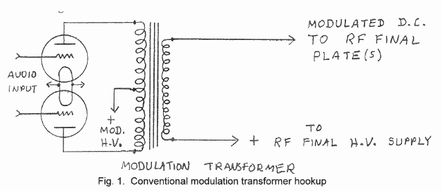
Apart from the quality of the audio transformers used, the circuit arrangement for voice communications transmitters and high fidelity transmitters is similar, although the coupling circuits in the communications transmitter may be deliberately designed to restrict the frequency response to something on the order of 300-3000 hz. However, there is one important difference in the way the modulation transformer is connected in broadcast transmitters compared to communications transmitters. In communications transmitters, including amateur rigs, the secondary winding of the modulation transformer usually carries the full DC plate current to the final amplifier stage. This familiar circuit is shown in the diagram below.
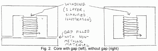
This circuit has the disadvantage that the final amplifier direct current flowing through the secondary winding of the transformer generates a "magnetic bias" on `the transformer core, and reduces the effective inductance of the transformer windings. This works exactly like a swinging choke in the power supply, wherein the DC flowing through the winding reduces the amount of inductance. To avoid magnetically saturating the core of the transformer, the laminations of the modulation transformer are stacked in such a way that there is a gap in the core, in exactly the same manner that power supply chokes are constructed.
This gap reduces the tendency of the core to saturate, but it also reduces the effective amount of core material in the transformer and thus reduces the inductance of the winnings. Furthermore, the gap in the core does not totally eliminate the DC saturation. Therefore the plate current flowing through the winding reduces the inductance even further. The low frequency response of an audio transformer is directly related to the inductance of its windings, so the core gap and direct current flow reduce the low frequency response of the transformer. For "communications quality" audio this is not considered serious and therefore most non-broadcast transmitters are designed to allow the plate current to flow directly through the modulation transformer secondary. For high fidelity audio, the low frequency attenuation caused by this arrangement is so severe that a tremendously oversize modulation transformer would be required. Other problems inherent to this scheme include phase shift distortion due to the restricted low frequency response of the transformer, and distortion caused by near-saturation of the transformer core on audio peaks, not to mention heating of the transformer winding due to the current flow. The end result is that the transformer often leaves a muddy sound on the audio and may run quite warm. The phase shift can greatly reduce the effectiveness of certain audio processing techniques, particularly the simple speech clipping often used in amateur AM transmitters. An additional problem sometimes associated with modulation transformers which carry plate current is a tendency to talk back. This is annoying to the operator and can degrade audio quality by generating acoustical feedback through the microphone. The popular UTC VM-5 and CVM-5 transformers are notorious for this.
These problems are eliminated in broadcast transmitters by isolating the DC plate current from the modulation transformer winding, allowing the modulation transformer to only carry audio. Since there is no DC flowing through the winding, the transformer core can be stacked just like an AC power transformer, without a gap. Such a transformer makes much more efficient use of the iron in the core, giving as much as ten times the inductance per winding compared to a similar size transformer with a gap in the core. The result is much better low frequency response for a given core size. In addition the transformer runs cooler, generates less overall audio distortion, is less prone to acoustical vibration, and the likelihood of accidental transformer burnout may even be reduced.
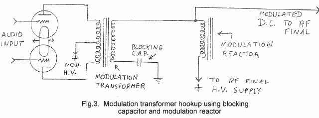
The DC is isolated from the modulation transformer secondary in broadcast transmitters by adding two additional components to the circuit. A blocking capacitor is placed in series with the modulation transformer secondary. A value of capacitance is selected to cause negligible rolloff at the lowest audio frequency within the specified response of the transmitter. To carry the plate current, a choke is connected between the final amplifier and the DC plate supply. This inductor is commonly called the modulation reactor. It is effectively placed in parallel with the modulation transformer secondary, and therefore must have sufficient inductance to not affect the low frequency response of the transmitter.
Fig. 3. Modulation transformer hookup using blocking
capacitor and modulation reactorIn a typical plate modulated transmitter, the DC blocking capacitor will have a value between 1 and 10 microfarad. The lower the modulating impedance (final amplifier plate voltage in volts divided by plate current in amperes), the higher the capacitance required for a given low frequency rolloff. Many of the older broadcast transmitters had excellent low frequency response with blocking capacitors as small as 2 mfd. Of course, more capacitance than needed, within reasonable limits, won't hurt anything. High voltage oil capacitors in this range are still available at flea markets at very low cost, since this capacitance is insufficient for most modern power supply filters. A good value to use is 4 to 8 mfd., which will work fine with about any modulating impedance encountered in a normal transmitter at amateur power levels. Since the high voltage to the RF final appears across the capacitor, the minimum DC working voltage should be at least 1.5 times the highest unmodulated plate voltage expected to be applied to the final amplifier, to be on the safe side.
The modulation reactor is the most difficult to find item required for this circuit. A typical reactor is rated at somewhere between 25 and 60 Henries at the maximum final amplifier plate current under normal operation. This is several times the inductance of a typical power supply filter choke. Amateurs have successfully used 10 Henry smoothing chokes as modulation reactors, although such a low inductance will reduce the low frequency response of the transmitter. One solution is to wire up several power supply filter chokes in series, although this tends to take up a lot of space and is somewhat of a JS setup. The preferred component to use is a real modulation reactor designed to go in a broadcast transmitter. With so many tube type AM broadcast transmitters going out of service at this time, these can be found if you are willing to look for them.
Circuit Variations
Figure 3 shows the most common modulation reactor circuit used in broadcast transmitters. In this circuit, the blocking capacitor is placed between the "cold" side of the modulation transformer secondary and ground. This provides a direct round return for the audio, independent of the high voltage power supply. In the conventional circuit (Figure 1), the audio is returned to ground through the hv power supply. The output filter capacitor is effectively in series with the modulation transformer secondary, and unless sufficient capacitance is used, this will limit the low frequency response of the modulator. More seriously, any residual hum in the output of the power supply will modulate the final amplifier and be audible on the signal. With the circuit in Figure 3 the hum output from the power supply is not placed in series with the modulator, and furthermore, the modulation reactor serves as an additional high inductance smoothing choke. Thus, the circuit in Figure 3 results in a substantial reduction of the hum level of the transmitter.
There is yet another advantage to this circuit if a common power supply is used for the class B modulator and final. Because of instantaneous variations in the load presented to the power
supply by the modulator, a strong harmonic distortion product appears at the centre tap of the primary winding of the modulation transformer. With the conventional (Figure 1) circuit, the "cold" side of the modulation transformer secondary is tied directly to the centre tap of the primary winding. Any harmonic distortion products existing at that point appear in series with the modulator and thus add distortion to the audio, especially at low audio frequencies. This problem can be reduced by using a large filter capacitor at the output of the power supply, or by using an additional section of filtering, consisting of a smoothing choke and another filter capacitor, between the centre tap of the modulation transformer primary and the cold end of the secondary. However, with the circuit in Figure 3, such precautions are unnecessary because the modulation transformer secondary is completely isolated from the RF final plate supply as far as audio is concerned.One disadvantage to the Figure 3 circuit is the possibility of modulation transformer failure due to a high voltage arc between the primary and secondary windings of the transformer. The "hot" end of the modulation transformer secondary is tied directly to the high voltage lead to the final, so that the secondary winding remains at the DC potential applied to the final amplifier plate. But the "cold" end is connected to ground through the blocking capacitor. When the high voltage is turned off, as for example when the transmitter is in standby, the blocking capacitor discharges along with the power supply filters; when high voltage is reapplied, the modulation transformer secondary remains momentarily at ground potential until the capacitor becomes recharged, through the combined inductances of the modulation reactor and modulation transformer secondary. During this brief instant the full DC potential of the modulator plate supply appears between the two transformer windings. This transient may be sufficient to cause an arc to occur and destroy the insulation between the windings. This is unlikely to occur with a transformer that has been maintained in a dry environment, since most modulation transformers are designed to withstand a substantial voltage difference between windings. Most broadcast transmitters use the circuit shown in Figure 3, and communications transmitters may use separate power supplies for the modulator and final with a substantial difference in output voltages. It is possible, however, that some modulation transformers may be designed specifically for a transmitter wherein the windings always remain at the same DC potential, and thus the insulation between windings may be prone to breakdown. Fortunately, this does not seem to be a problem encountered very often.
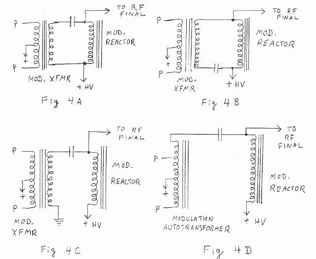
Figure 4 shows some variations of the basic circuit shown in Figure 3. In Fig. 4A, the "cold" end of the modulation transformer secondary is tied to the high voltage supply as in Figure 1, and the blocking capacitor is inserted in series with the "hot" end. The circuit in Fig. 4B is identical to 4A, except for the placement of the capacitor, which has been switched to the "cold" end. Both these circuits function much in the manner of the conventional (Figure 1) circuit, but the DC is blocked from flowing through the secondary winding. With this arrangement, several of the advantages mentioned with Figure 3 are lost, because the audio is returned to the high voltage plate supply as in the conventional circuit. However, the danger of modulation transformer breakdown described in the previous paragraph is eliminated.
The circuit in Fig. 4C is not recommended, since the modulation transformer secondary is tied directly to ground, and the full DC plate voltage to the modulator appears between the windings at all times, and as explained previously, could cause breakdown of the modulation transformer. Nevertheless, some commercially built AM broadcast transmitters use this circuit even though it presents no advantage over the Fig. 3 circuit. Fig. 4D shows how a reactor may be used with a modulation autotransformer in which there are no separate primary and secondary windings. This circuit offers the previously mentioned advantages of blocking DC from flowing through the modulation transformer winding, and allows the option of using separate power supplies for the modulator and final amplifier with a modulation autotransformer. However, the audio output from the modulation transformer is returned through the modulator high voltage plate supply, necessitating the use of a large value of output capacitance in the filter.
In Figures 4A, 4B and 4D, there is no DC voltage across the blocking capacitor. Theoretically, DC working voltage should be unimportant. However, transients and very low audio frequency voltages may appear across this capacitor under a variety of conditions, so the safe bet is to always treat this capacitor as if the full DC to the final appeared across it, and use the same minimum working voltage as required in Fig. 3.
Which Modulation Transformer to Use with a Reactor?
As previously explained, modulation transformers designed for use with a reactor have no gap in the core, and are not designed to allow DC plate current to pass through the secondary. However, transformers designed to carry DC through the secondary can be used with a reactor, and improved performance can be expected. In spite of the core gap, the low frequency response will be improved when the transformer is not called on to carry DC. The transformer will run cooler without the DC, and audible vibration will be reduced. I remember using and old UTC VM-5 which talked back terribly without the reactor, but it was practically silent when the reactor was wired into the circuit. Mike, NI4N was pleasantly surprised at the improvement in audio quality when he installed a reactor in the 1938 vintage transmitter built by his grandfather, which uses an old bottom-of-the-line Thordarson "ham radio" quality modulation transformer. In addition, it is likely that the power rating of a non-broadcast modulation transformer can be safely increased somewhat beyond the manufacturer's recommended maximum when a reactor is used. If a good broadcast quality modulation transformer designed to be used with a reactor is available, by all means use it. Otherwise, expect better performance with a conventional "ham radio quality" transformer when the reactor is included in the circuit.
If you are ambitious, you may be able to convert a gapped core to a solid core by restacking the laminations, sometimes referred to as "crosslaminating" a transformer. This is quite easy to do if the transformer is the open-frame type, and no potting compound is used on the winding. If the transformer is impregnated with varnish, it will have to be carefully heated to a temperature that will soften the varnish, but not damage the transformer insulation. If you are really ambitious, potted transformers can be heated, the tar removed, and then repotted after the modifications are made. Cross-laminating will greatly improve the low frequency response. However, it is recommended that you have some solid hands-on experience at assembly and disassembly of transformers, and all the necessary tools and workshop facilities, before attempting to tear apart something as hard to find these days as a good modulation transformer.
Thus ends Part I of this article. Next issue we will conclude with data on how to determine the amount of inductance required for optimum performance with a modulation reactor, and we will include catalogue data giving the manufacturers' ratings of modulation reactors produced by several prominent transformer companies.
(to be continued)
MEET THE AMers
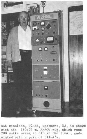
Bob Dennison, W2HBE, Westmont, NJ, is shown with his 160/75 m. AM/CW rig, which runs 200 watts using an 813 in the final, modulated with a pair of 811-A's.
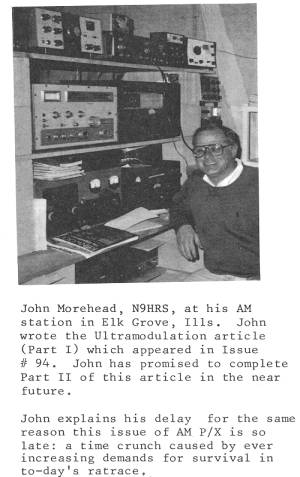
John Morehead, N9HRS, at his AM station in Elk Grove, Ills. John wrote the Ultramodulation article (Part I) which appeared in Issue # 94. John has promised to complete Part II of this article in the near future. John explains his delay for the same reason this issue of AM P/X is so late: a time crunch caused by ever increasing demands for survival in today's rat race.
YOU COULD BE USING A SIGNIFICANT
READABILITY IMPROVEMENT
ON YOUR AM RIG
BY SIMPLE PREEMPHASIS AND DEEMPHASISBy George A. H. Bonadio, W2WLR, 373 East Avenue, Watertown IVY 13601-3829
A Series on Amplitude Modulation Improvements
WHAT IT IS AND WHERE IT WORKS NOW
Installed preemphasis in our transmitters followed by traditional deemphasis in our receivers is a means to noticeably increase the copied intelligence on the voice, in spite of noises on the channel. Preemphasis in the transmitter and deemphasis in the receiver is standard in both TV audio and broadcast FM audio, at an FCC standard of "75 microseconds" (75 uS).
Because our normal voice energy peak is well below 1,000 Hz, often near 400 Hz, we Amateurs may use a preemphasis of better than the broadcaster's 75 uS. They are limited to 75 uS because of musical instruments, sound effects and the singing voice peculiarities. By contrast, we can go to a variable range of zero to over 330 uS, or 4.4X as much.
WHAT IS THIS IN DB?
At our voice frequencies, above 500 Hz, we can curve our response upwards, to a rising at +6 dB per Octave (+6 dB/O), all the way to a maximum of 3,333 Hz. Above 3,500 Hz we need to be going down rapidly.
Thus, we would have an ideal curve of about 0 dB, or flat, from 150 Hz up to 400 Hz curving upwards about +3 dB to about 800 Hz, then +6 dB more to 1,600 and, finally, +6 dB more to near 3,200 Hz. That is a total of about +15 dB on the high end. We can use this preemphasis only because our voice energy is falling off just slightly more than -6 dB/O in that range. Thus we are filling in space that nature left for us. Wasting it has been expensive.
WHAT DOES THIS DO FOR US IN OUR SPECTRUM
We, thus, change from our peak energy always being, from 120 to 600 Hz, to anywhere between 120 and 3,333 Hz. We will more effectively fill the portion of the spectrum that we have been poorly occupying. Our low levels of treble is why other signals moved into our sideband space. The slightly used spectrum is all there just waiting for us to fully use it. Financially, this is the cheapest way of buying dB's of readability.
The spectrum noises, in this range, increase at +3 dB/O. We can avoid having our weak treble being masked, by that noise, by preemphasizing at about a double rate, about +6 dB/O. Meanwhile, because of Amateur receiver deemphasis, by IF selectivity, is at an average rate of -6 dB/O, we will not sound shrill in either his, or our receiver. However, we will sound shrill into our own diode monitor because it does not deemphasize.
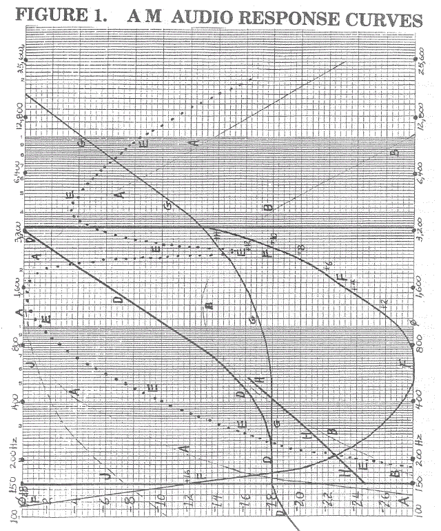
THE PROBLEM WAS RECOGNIZED BUT NEVER FULLY FIXED
We can see, in Figure 1, the original audio response of the DX-100, as curve A. It was peaked "for Amateurs" near 1,200 Hz. Notice that it was at 0 dB near 1,200 Hz, down to -6 dB at both 350 Hz and 5,000 Hz, then -12 dB at 210 Hz and 3,000 Hz. At 3,333 it was off by -3 dB. However, comparing with the idealized curve D, by redrawing curve A, lower, as B, the DX-100 was excellent between 400 Hz and 800 Hz. Overall corrections, then, would net a peak treble improvement of +16 dB near 3,333 Hz. However, the bass, of the DX 100, was almost non-existent below 200 Hz, going down at -10 dB/O near 220 Hz and -20 dB/O near 160 Hz.
In the DX 100, because of the transformer designs, all the bass, below 300 Hz, distorts, showing on scopes as severely kinked at 100 Hz. Its bass will not reach 100% modulation, gracefully, even with overdrive, but the treble is fine, when corrected to "flat."
WHAT WE HAVE PEEN PUTTING UP WITH
In Figure 1, notice how the Apache, curve E, became the "Scratchy Apache." It had two prominent audio peaks in the response. The deep notch, near 2,500 Hz, came from the LC audio filter. When I removed the filter's can, the notch moved back up to where I think that the circuit engineer designed it, to save the adjacent channels. However, apparently, a chassis engineer then put the can on, without checking the audio effects. Meanwhile the bass was poorer than the DX-100, (compare curve A with E) so it could sound "scratchy" with two narrow treble peaks at 1,600 and 4,000 Hz.
On Figure 1 we see other curves. Our voice peak treble energy rolloff is at over -6 dB/O. The typical idealized preemphasis curve, is almost straight, as curve D, between 600 and 3,333 Hz. The difference between the DX-100 curve B (not A) and the idealized curve D is calibrated as curve F between the usable range of 150 and 3,333 Hz. This great restoration of both bass and treble, by up to 16 dB, each, greatly enhances the readability. With this also comes more distinction of personality.
The range of the receiver deemphasis, by IF selectivity, is severe. Particularly we see that using our preemphasis substantially balances out our voice treble losses in the other fellow's receiver. Thus, we have his receiver restore our flatness or fidelity. It promotes reports of "armchair copy" instead of "I'm reading you pretty good". Meanwhile, of course, we had built our treble up by as much as +15 dB. This makes us that much stronger against the noises, which he knocks down by, say, near -15 dB. We have not increased our carrier power, nor have we overmodulated. However, with the same power, he now reads us through noises much easier.
TRY IT; THEY WILL ENVY YOU
The amount that it helps is very variable. You have to try it to believe It. Generally you will realize, against a flat response, about +3 dB at 800 Hz, +9 dB at 1,600 Hz and +15 dB at 3,200 Hz. Again, this depends upon where you started. We do need bass, and we do need treble. Without one, the other sounds overdone. For total readability we need "spectrum heard" which needs a range of at least 156 to 3200 Hz. We have been defeating ourselves by losing our weak treble in his receiver IF selectivity. Now, at minimum expense, we can recover this important loss of readability.
In Figure 1 the G curve is the standard Broadcast Preemphasis of only 75uS. Compare this with our curve D. G has only +5 dB at 3,333 Hz. Curve H is the low frequency roll off that our control would let curve D fall to. Curve J is the bass loss of the DX-100 that is directly from the low value of the audio capacitor of 510 pf onto the gain control.
Generally, on an average, I estimate about +7dB of effective improvement over the original factory circuits. +7 dB is about 5X the power. hat is, a 100 watt modern preemphasized carrier will get through noises, probably, as good as that old signal through a linear amplifier to 500 watts. We must realize that this is not a linear improvement, but it is always an improvement. At times it means being fully read when we would have been completely lost. I have demonstrated this in thunderstorm noises.
SOME OF US HAVE MADE POOR AM WORST WITH BIG CAPS
Most of our home reconditioned AM sets have had "the bass improved" by the insertion of larger blocking capacitors in the audio path. This had extended the bass without extending the treble. This is like enlarging only the left wheel on our chariot. Now we must balance the right side to avoid troubles. So, this procedure is adding both treble and bass to the typical AM set. With the formulas we can come out sounding both full and clear. Only one rheostat is used, and it is left where most of our friends say we sound the best.
A STANDARD FOR ALL OUR AM SETS
We do not want to keep returning the set to the workbench. We will correct the set to a flat response between 150 and 3,333 Hz, and roll off beyond those limits. Then we will use an outboard chassis of a preamplifier, to supply the surplus gain we will use up. A simple rheostat shunted by a certain capacitance will use that gain in sloping our preemphasis. Then we go through a simple compressor to let us up to 100 % modulation. This does not have the distortion of clipping. It squeezes the gain down so that we stay up to 100 % but lets the gain step up at a speed that does not bring attention to itself.
DOLLARWISE WHAT WOULD THIS COST?
Thus, for less than $100 we can increase our readability about +7 dB. That is at a cost of less than $15/dB, a real bargain. For about the same gain we would need to raise our antennas about another 120% higher, to 220% as high, for much over that price. We must remember that the incentive values, for increased signals, are not necessarily equal to the merits, in dollar costs. We would have to have an extremely low cost station to find a different and more economical signal gain, per dollar spent.
WHAT ARE THE ESSENTIALS OE PREEMPHASIS & DEEMPHASIS?
We must start m some standard. Every manufactured type of transmitter has its own frequency response. Most of those have been changed randomly. We cannot work from those curves. So, the most natural thing is to work from a flat response curve in any set. A flat curve is the easiest to duplicate. Electrically it is the most likely curve not to run out of its capabilities. We flatten the rig.
The preemphasis curve generating R & C will use up close to 30 dB of audio gain. See the lower end of curve H. We need a preamplifier between the mike and the set, to overcome most of this loss so that we can back off from the mike, in comfort. Each outboard unit will be usable into every other flat voice audio AM transmitter.
We need a compressor so that we do not overmodulate, or do not crush our audio into the square waves that I see and hear frequently, on the air. This is to help us get up to 100%, yet to keep stronger levels shrunk to 100% without obvious distortion, unlike clipping.
All of this is going to give us an apparent bandwidth of using 6.4 kHz and occupying a whole 7 kHz including trash. Thus we need several sections of filters to consume the energy we produce above about 3,200. We can, then, operate these stations at every 7.5 kHz apart. Surprisingly, this is not as wide as many of the stronger stations now on 75 and 40 meters. Frequently their trash sidebands will reach over ± 10 kHz, for a width of 20 kHz. These operators have no functioning Low Pass Filters in their modulation line. All the AM Broadcasting stations are now inserting filters in their lines.
WHAT IS THE NEED FOR A VARIABLE CONTROL
While we would like to be able to insert a fixed R & C to simplify our system, we do need this equalizer. We want to reach a curve similar to D of Figure 1. However, there are numerous mikes, voices, reflected sounds from desks, transformer losses and distances from the mike, all of which can affect the most appreciated level. Also, his receiver and loudspeaker enter into your choice.
It is easy. Put the control on so that you can read its positions from 7 am to 5 pm. While you operate you tell your friend where that pointer is set, and he will tell you where he prefers to hear you operate. After you have done this a few times you will see a preferred compromise setting. Leave it there. Log the setting.
There is an internal mike gain control which you will set for average use. To compress against temporary bad conditions just crowd onto the mike. You could switch your mike from
Low Z to High Z for extra gain. You will sound compressed but you will also sound much
louder.(To be continued)
EXCHANGE
HEATHKIT NOSTALGIA - A new 224 page paperback chronicles the history of the company that helped get many of us on the air, told in pictures and stories of and by those involved. $9.95 postpaid
WANTED: Urgently need Ranger final tuning condenser plus under shield. Also modulation and interstage transformers. H.J. McDade
WANTED: Old tube scopes dead or alive as long as CRT is not broken. Also could use a good multitester for my bench. AA4TW, Mike McCoy
WANTED: Need good copy of operating, service and maintenance manual for a Hewlett-Packard model 524-C electronic counter. Will borrow, make copy and return to lender or pay reasonable price. J. Harvey Mewborn W4KBQ
HELP! HELP! HELP! HELP! HELP! HELP! HELP! HELP!
Most AM'ers and collectors of vintage equipment own at least a few older books and magazines to help capture the history of the era when our style of radio was mainstream. Many of us are as fond of our books as our actual equipment. Books and magazines no longer in publication contain a wealth of information that is unavailable elsewhere, and if these books are ever destroyed, this knowledge will be lost for ever.
Even though we go to extreme effort to care for our books, they may still be in grave danger. I just discovered that my entire book and magazine collection has silently become infested with silverfish. These insects eat away at the glue that holds the books together, and you may not even notice them until the damage has already been done. I am reluctant to spray insecticide directly on the books for fear of damaging the paper.
Does anyone have any suggestions how to safely exterminate these pests? None of the local merchants who deal with insecticide could convincingly help me. For the benefit of our readers, any solutions to this problem will be published in AM P/X. And please take a careful look through your book collection to make sure you dont have this problem!