
Issue 100
Scanned and prepared by Grant/NQ5T
Intruder Takes Over 1860 Khz
In recent weeks an intruder has appeared on 1860 khz, disrupting the Gateway 160 metre Net and bulletins transmitted by Vern, WA0RCR. A strong unmodulated carrier on frequency repeatedly shifts upwards about 1 khz and transmits a burst of what sounds like digital data. The signal is nearly identical to radiolocation beacons monitored on 1625, 1700, 1760 and 1785 khz. Similar sounding signals have periodically been noted near 1960 and 1997 khz.
Vern's signal is one of the loudest on the band, usually readable even under severe thunderstorm static. This intruder has at times rendered Vern's signal virtually unintelligible. Audible throughout the hours of darkness, at times it becomes the strongest signal in the entire 160 metre band.
The FCC's monitoring station at Powder Springs, GA, was called and asked to monitor 1860 khz. The person on duty stated that the signal was "legal"; he said it was an "experimental navigation beacon operating off the coast of Texas." He was unable to give the callsign of the station, its licensee or the transmitting power, but he indicated it is licensed under U.S. jurisdiction.
This intruder leaves several unanswered questions. Readers will recall that several years ago the FCC reallocated the top half of 160 (1900-2000 khz) to the Radiolocation service. Amateurs were allowed to continue operating on those frequencies in a shared secondary status, on the condition that they cause no harmful interference to radiolocation beacons. You may have noticed the cluster of beacons now in operation between 1910 and 1925 khz, with occasional signals heard elsewhere in the top half of the band. These signals are perfectly legal, and amateurs are obliged to avoid causing them harmful interference under our secondary status of allocation.
The beacons above 1900 khz have caused little disruption to amateur operation since most 160 metre operators seem to prefer the low frequency end of the band, which becomes congested on winter evenings while the top end remains sparsely populated. This lack of congestion renders the top end of 160 ideal for AM operation, and this part of the band has become increasingly popular among the AM operators, although AM remains widely heard in the vicinity of 1885 khz.
The 1860 khz beacon is of particular concern because the spectrum below 1900 khz is allocated exclusively to amateurs and radiolocation is not supposed to operate there at all. Why has the FCC apparently licensed a radiolocation beacon in this segment? We lost exclusive use of 1900-2000 khz to the radiolocation service. We stand to lose the upper half of the band entirely if the radiolocation service continues to expand in the future. Part of the 220 mhz band was taken from us entirely. Has the FCC now decided to take away still more amateur spectrum, without even bothering to go through the reallocation process? If this intruder is allowed to remain, it will set a dangerous precedent indeed. Of additional concern to the AM community is the fact that if radiolocation beacons begin to clutter up the lower half of the band, SSB operators will migrate to underused frequencies above 1925 khz and AM operation on the top end will face increasing congestion and QRM hassles.
A phone call to ARRL Headquarters yielded no results, but the local ARRL Official Observer coordinator, who was unaware of the problem, promised to investigate. We can all get involved in this issue. Take a few minutes to tune your receiver to 1860 and listen for yourself. If you feel alarmed at what you hear, pass along your concern to other hams who may not be aware of it. Bring it up at local club meetings. Contact ARRL and express your concern. Most importantly, drop your Senators and Representative a line and demand to know why the FCC has illegally licensed a radiolocation station in a part of the amateur spectrum where such stations are specifically excluded. We must not sit idly by and allow this unlawful invasion of amateur radio spectrum to go unchallenged.
SCREEN IMPEDANCE NEGATIVE FEEDBACK
Bacon, WA3WDR, 8 Paulding St., Huntington, NY 11743
It is generally believed that a very stiffly regulated screen voltage is required for low distortion in a tetrode amplifier stage. However, I have found that distortion decreased when I added unbypassed 820 ohm resistors in series with the screen grids of each of the (two) tetrodes in my modulator. Note that there are two unbypassed resistors, one to each screen grid, NOT one to both. I tried one resistor feeding both screen grids, but that increased distortion substantially. [See Figure 1]
When a resistance is placed in series with the screen grids like this, the screen voltage will drop about 60 volts during modulation (more on this later). The precise amount of this drop will depend on the control grid voltage AND the plate voltage, because the screen competes with the plate for that stream of electrons coming through the control grid.
There will be a natural relationship between the plate current and the plate voltage, but if distortion or reactance interferes with that relationship, the plate will be either higher or lower than it should have been. If the plate is higher than it should be during conduction, it will attract more of those electrons and the screen current will be lower than it would have been. The reduced screen current will produce less drop in the screen resistor, which will raise the screen voltage. The increase in screen voltage will produce a large increase in plate current, which will pull the plate voltage lower. The reverse happens if the plate voltage is lower than it should be during conduction.
Because of the screen resistors, the tube fights for the natural plate voltage swing. Therefore this is a form of voltage feedback responding to the plate voltage versus control grid drive.
There are a few potential problems with this screen impedance method of negative feedback.
First, there will be audio on the screen grids, out of phase with the voltage on the control grids. This will cause a substantial increase in input capacitance on the control grid. If the driver circuit impedance is too high, this could cause some high frequency rolloff.Second, you will need higher screen supply voltage to get full output. Screen voltage drops when the tube conducts, so the supply voltage must be raised to compensate. Of course, you may choose to overcompensate if it gets you more output, as long as you don't overheat the screen. Note that the screen voltage is lower when the tube is conducting heavily; the increase in screen dissipation is small.
Third, there will be a decrease in gain, because this change adds negative feedback. You CAN get the same output in class AB1, by raising the screen supply voltage, but you will need more control grid drive voltage to get full output. Remember that you will have to increase the negative bias on the control grids when the screen supply voltage is increased!!!
Fourth, you will not achieve optimum results unless the screen supply is regulated. Screen current from one tube should not affect the screen voltage of the other.
Fifth, if your modulation transformer has a high impedance ratio (4:1 in many rigs) you may not get more output from your modulator with this change. However, you should get cleaner audio.
I am using 8417's in my modulator. These tubes are similar to the EL34/6CA7, but are a bit more powerful. Before the change, I had 975 volts on the plates, 300 volts on the screen, and about -25 volts bias on the control grids. The modulators drive an impedance of just less than 4000 ohms plate-to-plate, and I use cathode follower control grid drive.
Screen current varies from about 8 mA with no audio, to somewhat over 35 mA average at full output. This means about 60 mA at the crest of the peak.
Starting with regulated 300 volts, I added a single 820 ohm resistor from the regulator to the two screens in parallel. Distortion went up, so I took that resistor out. Then I tried two 820 ohm resistors, one to each screen. Distortion went down, but maximum output dropped too, as I expected. Then I raised the regulator output to 380 volts. Distortion stayed low, but output was actually greater than before the mods. Of course I had to increase the negative bias to -30 volts when I raised the screen voltage, to maintain acceptable resting current.
Figuring 60 mA peak, the screens never get less than 331 volts (0.06 amps x 820 ohms or about 49 volts less than the 380 volt regulator output), which is higher than the 300 volts it was before, which accounts for the increase in output.
Distortion was reduced and output increased. It sounds quite clean to me, cleaner than it was before the change.
1992 AM Forum at Dayton
The third annual AM Forum at the 1992 Dayton Hamvention took place on Saturday afternoon, April 25. Once again, Meeting Room 7 was packed to the limit, with standing room only at the rear for latecomers. The room was more comfortable this year, thanks to the two ceiling fans installed since last year's Forum.
This year's Forum started with an unusual announcement by K8AFP. He stated that he was to leave soon for an extended tour of overseas military duty, and he was looking for a trustworthy ham to use his Globe King 500C and give it TLC while he is out of the country!
The program started with a slide show presented by Dale, KW1I, featuring the elaborate station of Sam, W6HDU, which consists of several separate operating positions with an array of vintage equipment, including a couple of broadcast transmitters. Slides also featured the stations of Andy, WA4KCY, and Jim, W4PNM.
The second part of the program was a panel discussion, led by Don, K4KYV, editor and publisher of The AM Press/Exchange. Panelists included Pete, WA2CWA, John, WB5HRI, Jim, W4PNM, and Skip, W7YOO, representing the AM community over a wide geographical area. A number of topics were discussed, particularly the problem of interference between AM groups operating near the same frequency in different parts of the country, and the pros and cons of all stations in an AM QSO zero-beating the same frequency (to minimize spectrum occupied by the QSO vs. the inconvenience this would cause to stations operating crystal control). A brief question and answer session with the audience followed the prepared discussion.
Time ran out before members of the audience had a chance to get together for individual conversations, so a dozen or so of those present joined Don and Dale that evening for the traditional pizza dinner at a local restaurant, where the small group discussions were able to continue.
Once again, the AM Forum at Dayton was an unqualified success, one of the high points of the hamfest. Already, many of those present have mentioned looking forward to next year.
Tube Installation Hints and Testing Tubes
by Dr. David Knepper, W3BJZ
We, too, echo Don's remarks in his recent article on extending tube life by paying attention to the rated tube's filament voltage. The heart of every vacuum tube is its filament. Improper operation of the filament will ultimately shorten the tube's life.
Although small variations in filament voltage are compensated for in the designing of tubes, most satisfactory results are obtained when filaments are operated at their rated voltage. Lower voltage limits the electron emission of the filament and generally results in the over-heating of the tube, while higher voltage will rapidly dissipate the supply of thorium in the filament.
One should use sockets with large sweeping contacts. Poor contact between socket springs and tube prongs will cause a drop in filament voltage. Heavy, well-soldered leads are very essential. If possible carefully light the tube to its rated filament voltage for ten minutes before applying plate voltage for the first time. Preheating of the filament after the first installation will not be necessary.
To give doubtful tubes (especially those purchased at hamfests) a partial emission test in one's transmitter, the following test can be employed. Most amateurs have or can easily obtain a 6.3 volt or 10 volt transformer. In the case of testing a tube which has a 7.5 volt filament, replace the 7.5 volt transformer with the 6.3 volt transformer. Then, without making any other changes in the transmitter's operation, note the readings of the meters in the grid and plate circuits of the tube being tested. There should be only a slight drop in the plate current while the grid current may drop to one-half its former value and the tube would still be satisfactory condition. Should the grid current drop in excess of one-half the original value, the filament emission can be considered as below normal and the tube should be taken out of service.
In the case of 10 volt tubes, when the filament voltage is dropped to 7.5 volts by substituting transformers, the grid current can be expected to drop to approximately one-half the normal value. Should the grid current drop in excess of one-fourth (1/4) the original reading, the tube can be considered as having low filament emission. This information is based on tubes being operated as Class C amplifiers with the normal rated plate current.
This "test" of the filament's integrity is similar to that employed by the common tube tester. The so-called "life-test" used to measure the current flow in the plate when the filament voltage is reduced under "test" compares quite closely to the test performed and recommended by the Taylor Tube Company many years ago in the preceding paragraphs. Actually both methods to determine the integrity of a tube's filament measure the amount of filament reserve when the filament voltage is reduced as indicated by the drop in both the plate and grid current meters.
Needless to say, the integrity of the tube itself actually begins in manufacture. Perhaps, this is why many hams are experiencing premature failure with the newly introduced foreign tubes entering, this country from China and Russia. If the materials and assembly are deficient from the start there is very little that can be done to preserve the tube from premature failure once the tube is put into service.
The real culprit is the operator himself. As EIMAC so cogently states in their literature: "The technical data sheet for each tube type gives the basic maximum ratings for each class of service. Also on the technical data sheet will be found references to cooling air and maximum temperature and mechanical considerations as they may affect life. Careful observance of the information on the data sheet will avoid damage to the tube and shortening of its useful life."
In general, EIMAC continues, "the tube ratings are so chosen that operation within the ratings will give a minimum of 1000 hours of guaranteed life. the typical life expectancy is therefore considerably greater and will depend upon a great many factors. In general, operation below the maximum ratings will increase the life expectancy o f the tube. This is especially true with reduction in the plate dissipation of the tube. Very roughly sneaking, the life expectancy will go up directly as the plate dissipation and total watts being handled by the tube go down." For a more thorough discussion see: EIMAC's publication, "The Care and Feeding of Power Tetrodes" published in 1951. Reprints available from the author.
From personal experience while serving as a ground communications repairman with the Air Force back in the 60's, I recall that our transmitters were never shut-off. Many of the units used the popular 4-1000 tube in the final and modulator sections. Tube replacement from filament failure was minimal. The amplifying tubes in all of our two to five kilowatt units were replaced once the output dropped appreciably. At our receiver site the long bays of R-390's and SP-600JX's were never turned off. Again, tube replacement was only necessary when the unit failed to meet specifications.
My own opinion to extend your collection of expensive transmitting tubes would be to stand the tubes in upright position to prevent filament sagging and to wrap the tubes carefully to prevent breakage. Lighting the filament occasionally without applying grid and plate voltage does very little good. Swapping tubes around is perhaps the best advise to follow. Sticking to the more conventional and readily available tubes like the 813, 4-250A, 811A, etc. rather than the more exotic tubes, especially the ceramic types, when building that new rig is probably something to think about. I am sure that the final word on this subject has yet to be written. 73.
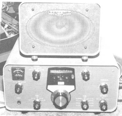
AN OVERLOOKED RECEIVER
By Marty, WB2FOY The Heath Collector
I love to collect Heath gear and besides Heath making some of the most popular transmitters they also made some of the best receivers. The receivers were known as the SB series.
They started out with the SB-300 in January of 1964. A few years later the SB-303 came out as a solid state receiver. Each time the new line came out it was better defined with more improvements. I own a SB-300, 301, and 303.
More 303's were sold due to it being solid state and the SB line became very popular. These receivers were small, lightweight, very selective, sensitive and stable. They used crystal filters; one for CW, AM, & SSB. These filters, back in the 60's, sold for about $20.00 each and today they can still be bought for about $100.00 each.
The SB line of receivers took on the look of the Collins S-line. It was sometime called the Michigan S-line, or the poor man's S-line.
Now, one might say that there is no comparison between the Collins S-line and the Heath SB series but, if the kit receiver was built right and aligned to specification, it would perform just as well as the Collins or even better. Like anything else, you got out of it what you put into it. The Linear Master Oscillator (LMO) was preassembled. It was built and pretested by TRW. If you buy a Heath SB series receiver today at a flea market, look it over good and make sure it was put together with care. If you find that it wasn't put together with care don't overlook the possibility that it still may be good for parts. These small receivers are big performers.
Most like to collect National, Collins, Drake, etc.., but the Heath SB series is always overlooked. When you buy a Heath, you usually get a lot for your money.
The next time an opportunity comes up and a SB receiver is spotted, don't pass it by, give it a try. You may be surprised at what you have been missing.
Besides being a low band receiver, Heath also made a 2 and 6 meter converter for the series that plugged into the back of the unit at the accessory socket. Switching for the different antennas was made possible with a switch on the front panel. Tuning was done on the ten meter band. These receivers can be used with any transmitter. They are simple and easy to fix. And they are lightweight so you don't have to bust your butt trying to move it.
One more important thing. We need to save and collect Heath gear. They are not in the HAM radio business anymore. We need to save our great past.
Love to hear from all who have any SB series receivers. If you need help with a problem drop me a line.
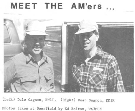
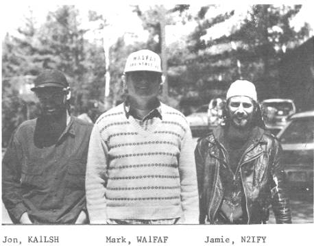
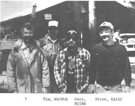
MEET THE AM'ERS
(Photos taken at Deerfield by Ed Bolton, WA3PUN)
Dale Gagnon, KW1I; Dean Gagnon, KK1K
Jon, KA1LSH; Mark, WA1FAF; Jamie N2IFY
Unknown; Tim, WA1HLR; Gary N2INR; Steve, KA1SI
NOW AND THEN
THE BREADBOARD TRANSMITTER
PART VHarry Wells, AA6PP
Prepared by R. De Miranda, WB6UBD
METERS
Personally l like Weston, Jewell and Readrite meters. These belong to history now and fit my taste best. You have wig permission to use Triplett, Roller-Smith, Phaostron, Simpson or even Japanese meters, but glorious Weston model 301 meters cost a buck and down these days. These meters were the height of snobbery in the good old days and are still top quality if they have not been abused. I can't resist and l must have 200 of them. I remember when a working man couldn't afford them and maybe had a single Jewell meter and a Readrite or two.
The Weston 301 is a 3-1/2 inch diameter meter, but Jewell made a meter that was 4 inches and it was somewhat cheaper than Weston so it was quite popular. Old time rigs were often large and the smaller meters got lost on the panel and in such case Jewell was both cheaper and better. My 75T final uses a pair of 4 inch Jewell meters and a pair of 3-1/2 inch Jewell meters. A few gears ago I ran into a set of 3 five inch diameter Jewell meters in brand new condition and two them were usable in a transmitter. I was so shocked I don't recall where or how l got them now. I know l went home with my head far up in the clouds because l had never seen anything like them before and they were in immaculate condition. They look grand in a chassis type breadboard rig.
As for the Readrite meters they were all of iron vane construction and very cheaply made, but they worked even if they mostly did read wrong. With a little luck a kid could afford at least one. With a lot of luck you could win one by entering one of Hugo Gernsback's contests where they were offered as prizes. Since l was around when the guys still had to use them they look at home in breadboard to me, particularly in small rigs. If you like to suffer you can use a flashlight lamp or a panel lamp depending on the current range you need. Those in real poverty managed in this way. It doesn't say how much, but does indicate maximum or minimum current.
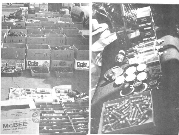
A TRIP TO THE SCARS SWAP MEET
The Southern California Antique Radio Society Swap Meet. A general view of the parts dealers layout. A paradise for vintage radio collectors and builders. Includes lots of receiving and transmitting parts. This place looks full of what many of us hope to find a dealer or two selling at Dayton! Photo on right shows what the author bought that day.
On November 16, 1990, the day after I had actually finished this article and also Saturday the 17th the Southern California Antique Radio Society had its year end swap meet and other club activities. I was able to attend on Friday and what l bought and saw, is good news to anyone that builds or operates vintage type gear. You can still get tots of great vintage parts cheap, including tubes.
There is a vintage parts dealer who has attended a number of vintage meets for some years. He had 2 National type B dials and l bought the best one for $3.00. He had other vernier dials and there were more Nationals at other sellers for up to $10.00 as well as 2 Pilot vernier dials. Our parts dealer had maybe 30 or 40 TRF dials. Eby and Pilot breadboard sockets in 4, 5, and 6 pin total a dozen or so and l bought a couple of Pilot 5 pin as well as a Pilot and an Eby new in box. NIB $1.50 each, used $1.00 each. Hammarlund ceramics used; 6 or 7 available at $1.00 each. I bought 5. A box of more than 80 new IRC metalized resistors were a rare find in assorted values. $10.00 for the box. I took 'em all. He had a box of small plug-in coils for winding (or rewinding) for your exciter; a substantial quantity of molded mica transmitting capacitors with a few Dubilier Micadons mixed in. He had a few tubes, but nothing interesting except a quite rare Sylvania 865 transmitting tube for $ 5.00. This is a collectable rather than a usable and I took it, too.
Next stop a ham who said he had a huge lot of transmitting tubes and was disposing of just a few that he considered excessive. I bought a pair of Amperex HF-100 (quite rare now) for $10.00 and a pair of United 966 rectifiers new in box for the same price and a single United CV-11 for $2.00. Finally he had a B eliminator stacked filter choke assembly in fine condition for $1.00. Yes l did. I didn't buy a pair of 813s for ten bucks as I have many already. Ditto a few, other tubes he had.
At another seller a couple of small dials for $1.00 each and at the bookseller I found a needed copy of Hugo Gernsback's Short Wave Craft for $7.00. Eight bucks worth of other new in box collectables and that was the end of my money. But there were other interesting things for sale.
One fellow had a box of about ten brand now VT 4C/211 tubes for ten dollars each. Another had 5 bands of kilowatt tank coils still in boxes and they looked new. I didn't ask price. There were a few communications receivers around and a Harvey-Wells Bandmaster Deluxe as well as a Hallicrafters HT-9 transmitter. These items just noted in passing. One fellow had 2 big boxes of wax dipped paper capacitors, new, which were used in all kinds of equipment in the late 1930s.
Of course there were large quantities of vintage AC and battery broadcast receivers and some repair parts for them. Nothing whatever was seen of small transmitting variable capacitors. However, this was the off day, the big swap meet is Saturday morning and much, much more will be available. Lots of sellers from out of town and out of state will not arrive till late Friday night. I cannot attend on Saturday, but it's just as well since l already spent all of my money.
For those who can attend ham convention and vintage radio club swap meets it appears there is no real shortage of parts, and not much competition for those available with exception of transmitting tubes. Who builds anything today?
Because I cannot attend Saturday meets and that is the day for them I've not been to any for some years. The Friday swapmeet at the yearend SCARS club activity is new in 1990. What I found is hope and good news for anyone building vintage type gear. Even so you can scrounge around at home garage sales, surplus dealers, local ham club swap meets and such and come up with very little for a lot of time and effort. But sometimes you fall into a treasure trove even today, too. Try it.
SAFETY
Too many a careless ham has put his family to the permanent sorrow of his loss and strain of his funeral. Breadboard transmitters use high voltages. Even low power rigs use high voltages. The best available information says a current of about 8 milliamperes through the chest area can stop your heart or cause fibrillation. There is also the problem of small children and pets in many homes and these must be taken into consideration, too.
A neon bulb connected to the high voltage through a suitable dropping resistor and located on the rig where it cannot be missed when reaching in to change a tank coil, or whatever, can be a life saver. They will maintain a glow with only a few microamps of current as the filter capacitors bleed off after the high voltage is off and they are not subject to secret catastrophic failure.
My 75T final in addition to the neon bulb has the link adjustment on the final tank arranged so when it is turned out of the coil for coil changing the high voltage is automatically shorted and this is a very desirable arrangement. 1800 volts and a 20 microfarad output filter capacitor make an unnerving flash and crash and I am more anxious to avoid that than the high voltage. Because of that I never forget to turn off the high voltage and my memory is noticeably defective .
Safety for everyone around deserves as much thought and ingenuity as anything else in a breadboard, and maybe somewhat more. Where an open breadboard must be located in a family environment a key lock on the AC power can prevent any possibility of kids turning the high voltage on when you are not around. They often do a no-no when alone for a few minutes. Enough said. Either you will or you won't pay attention, but breadboard rigs, except for enclosed types, have exposed high voltage and they MUST be recognized as a safety hazard.
CONCLUSION
For close to twenty years I've been using breadboard rigs exclusively at this location on 160, 80 and 40 and I used to operate a bit on 20 CW with my 35 watts exciter. I gave up 20 because my FBXA National receiver couldn't hear much with a 160 meter wire and the other bands kept me plenty busy. On 40 I run up to 400 watts input to a pair of Eimac 75T's. I admit I bomb my own set somewhat on low channels, but I use the TV mast as the support for the voltage end of my 160 meter wire which I use on all bands. Separation of the wire from the TV array is only four to five feet and for years previously I used a pine tree and the separation was about 3 feet. You certainly can use breadboard rigs today under the proper conditions. Since I only have experience with my present location the rigs which are satisfactory here might be a disaster in another location. My suggestion for anyone who wants to try this very unusual aspect of ham radio is to be conservative in design and operation of such rigs. Properly built and sensibly operated I believe a lot of fellows can do it with no pain.
None of my rigs has any external attempt to control harmonic radiation. No shield cages. No antenna tuners, no low pass filters and no power line filtering. No complaints from the neighbors about TVI either. The 160 fone does get into a record player at parties next door.
Just getting started with breadboarding now is admittedly a hard way to go because of parts scarcity. Getting into it with the intent to build just one rig is somewhat a waste of time since it takes several rigs to accumulate experience, and over that time you will also acquire a stash of parts to ease the construction of the breadboard which will be the acme of all breadboards.
Very many will read this article, but few indeed will heed the call to put some adventure back into your ham activities. If there is anyone at all out there who is actively building and using breadboard today I sure would like to hear from him. I suspect I am the only one on the planet and it's sad to be the only one left.
END OF SERIES
Missouri ARRL Convention Seeks AM Forum
The Missouri ARRL State Convention will be combined this year with the Ozark Regional Hamfest at Springfield, MO on Saturday, August 1, 8AM to 5 PM, and Sunday, August 2, 8 AM to 1 PM. This hamfest is all indoors, with assistance available for moving heavy items in and out of the fleamarket.
Hamfest organizers are looking for someone who will put on an AM Forum or a forum on vintage equipment. Interested persons should contact Larry Howe, KB0HIB.
Given the success of the Dayton AM Forum, this is an excellent opportunity to expand the promotion of AM as we strive to firmly reestablish AM as an integral part of mainstream amateur radio. There is a lot of AM activity on 160 and other bands from this part of the country. Can some of you help make this AM Forum a reality?
EXCHANGE
WANTED: Clean Collins 75A-2 and speaker. Tom Russell, K8LZF
WANTED: 50 to 100 General Radio banana plugs for breadboard transmitter projects coils. Need standard size as used on commercial coils made for ham rigs. 6-32 threaded hole or stud OK. Minimum stud length 7/16 inch. (Apparently he is looking for the smaller size, not the jumbo size used on the kilowatt size coils - Ed.) AA6PP, Harry Wells
WANTED: Info on Freed transformer with #118-507 (and no other markings) on body. Successor company to Freed can't identify. Weighs about 25 lbs with 4+3 terminals on bottom. John, N9HRS
FOR SALE: Knight Spanmaster $40 postpaid. Herman Gibbs KD8PD
WANTED: R.F. deck parts for a 30K1 like the tank coils, variable condensers, and band switch. Also need several 75TH tubes. Need brass reduction tuning shaft for a RME-45B receiver, or junker. Also wanted manual (copy ok) for the SONAR SRT-120 transmitter, speaker for RME model 69 receiver. Any Collins speakers and parts. David Knepper
FOR SALE: Estate of Bill, W2SOT: 32V2 with manual; HQ120 receiver with manual; Oscilloscope from kit, model IO-102, with book; EICO signal generator 75 khz-150 mhz; Realistic High Compliance 4" speaker 80-15,000 hz, 8 ohms; Muffin fan 115v. 60hz, 14 watts 4 3/4"; Icom mike IC-SM5 Electret PTT sw; 100 khz crystal bar 8 prong; 10 cans, each 100 mf @ 400 v, 150 @ 350, 20 @ 250, 50 @ 250; 15 boards, each 8 hiP. diodes w/47k res. & .001 ceramics; soldering gun 2A @ 120 v Wen #288; Wall plug DC, 12 watt, 9.75 v @ 650 ma & 5w, 9v @ 9 ma; Eimac 304TL, Ken-Rad pair 813's, EL8; LaFayette HE-45a 6m transceiver. None modified. George, W2WLR,
WANTED: Western Electric transformers and oil caps. Also Triad HS-1, HS-32, HS-52, UTC LS-40 and other high quality audios. Joe, N4WQC
WANTED: Hallicrafters SX-28, SX-111, SX-122, SM-40 S meter, Knightkit Ocean Hopper with or w/out coils, any condition, reasonable not ridiculous price. Bill Culligan, N1DJR
FOR SALE: BC-610 RF deck cabinet; restorable Hallicrafter S-36A; very clean 6 1/2 ft. X 30" deep 19" rack on castors; 2 smaller 19" racks also 30" deep on castors (approx size of Johnson Desk KW) with white Formica tops, nice, clean, handy doubles as workbench, 4 grounded electrical outlets built in; Knight 600A tubetester w/ manual $45; Hewlett Packard 202A sine, square, sawtooth wave generator $45. Many vintage handbooks, reference & textbooks, QST, CQ, Radio, RadioElectronics, Radio News, etc. Now compiling lists of these as well as numerous transformers (plate, filament, audio, interstage, modulation reactors), oil filled caps, military surplus, antique test & radio equipment, different sizes of chassis, and many other parts. SASE for lists. WANTED Sylvania 6JB6 tubes & clean working Ranger, preferably Ranger II; buy or swap.